
Automatic control method and system for automobile lamp

A technology of car light control and body controller, which is applied to vehicle components, transportation and packaging, optical signals, etc., can solve the problems of potential safety hazards, electric adjustment methods that cannot respond to car-related information in a timely manner, and cannot achieve precise control. Achieve the effects of enhanced accuracy, improved safety and reliability, and convenient function expansion

Active Publication Date: 2012-11-28
CHERY AUTOMOBILE CO LTD
View PDF0 Cites 0 Cited by
  • Summary
  • Abstract
  • Description
  • Claims
  • Application Information

AI Technical Summary

Problems solved by technology

[0003] The existing electric adjustment method can not reflect the relevant information of the car in a timely manner, and also requires human participation to complete the adjustment, which cannot achieve precise control, causing certain safety hazards

Method used


Image

  • Automatic control method and system for automobile lamp
  • Automatic control method and system for automobile lamp
  • Automatic control method and system for automobile lamp

Examples


Embodiment 1

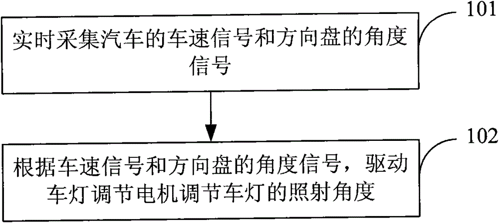
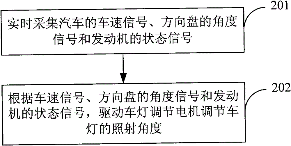
[0043] see figure 1 , this embodiment provides an automatic control method for vehicle lights, including:

[0044] Step 101: collecting the speed signal of the car and the angle signal of the steering wheel in real time;

[0045] Step 102: According to the collected vehicle speed signal and the angle signal of the steering wheel, drive the light adjusting motor to adjust the irradiation angle of the light.

[0046] Wherein, there are usually two headlight adjustment motors, one is a left adjustment motor, which is used to adjust the irradiation angle of the left headlight of the automobile, and the other is a right adjustment motor, which is used to adjust the irradiation angle of the right headlight of the automobile. The vehicle light in the embodiment of the present invention refers to the headlight of the automobile.

[0047] In step 102, driving the vehicle light adjustment motor to adjust the illumination angle of the vehicle light, specifically, can be realized throug...

Embodiment 2

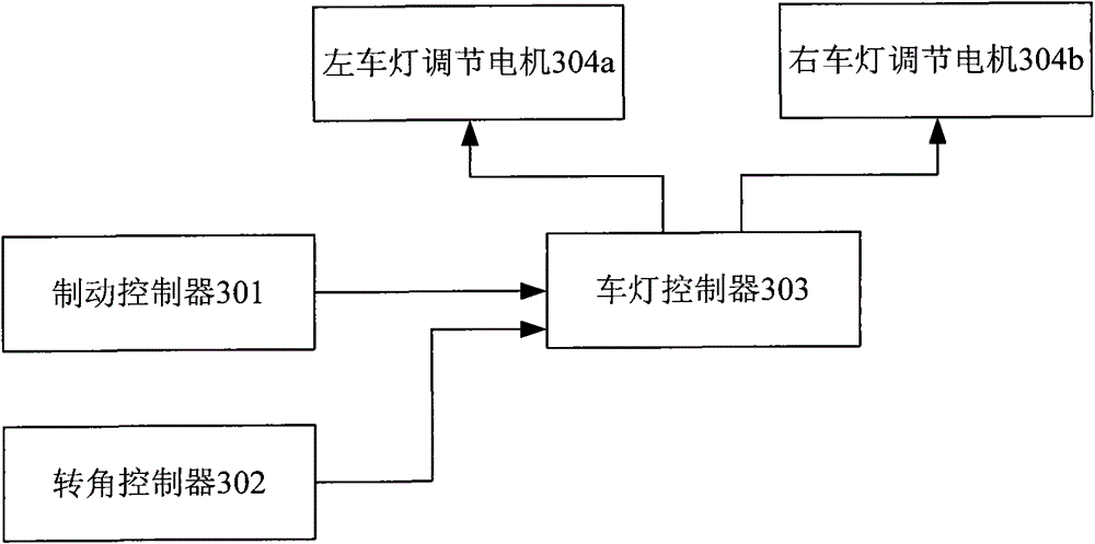
[0060] see image 3 , this embodiment provides an automatic control system for vehicle lights, including:

[0061] Braking controller 301, used for real-time acquisition of vehicle speed signals of automobiles;

[0062] Angle controller 302, used for collecting the angle signal of the steering wheel of automobile in real time;

[0063] The vehicle light controller 303 is connected with the brake controller 301 and the steering angle controller 302 respectively, and is also connected with the vehicle light adjustment motor, and is used to receive the vehicle speed signal from the brake controller 301 and the steering wheel signal from the rotation angle controller 302 The angle signal, according to the vehicle speed signal and the angle signal of the steering wheel, drives the lamp adjustment motor to adjust the irradiation angle of the lamp.

[0064] Wherein, a policy may be pre-configured on the vehicle light controller 303, and the vehicle light adjustment motor is driven ...


PUM


Abstract

The invention discloses an automatic control method and a system for an automobile lamp, belonging to the field of automobile automation. The method comprises the following steps of: collecting the speed signal of the automobile and the angle signal of the steering wheel in real time; driving the automobile lamp adjusting motor to adjust the irradiating angle of the automobile lamp according to the speed signal and the angle signal of the steering wheel. The system comprises a braking controller, a corner controller and an automobile lamp controller. By collecting the speed signal of the automobile and the angle signal of the steering wheel in real time to drive the automobile lamp adjusting motor to adjust the irradiating angle of the automobile lamp in the invention, steer condition of the automobile can be understood in real time and controlled and adjusted correspondingly without artificial operation, thereby the automatic control of the automobile lamp is completely realized, andthe safety and reliability of traveling are greatly improved.

Description

technical field [0001] The invention relates to the field of automobile automation, in particular to an automatic control method and system for vehicle lights. Background technique [0002] Generally, the headlights of automobiles have a fixed range of illumination, and the angle of illumination cannot be changed. When the car is driven on a bumpy road and the wheels are randomly excited, or the load on the car body is unbalanced, and the car is performing operations such as acceleration and braking, the distance between different parts of the car body relative to the ground will continue to change. At this time, the front of the car Illuminating according to a fixed range of illumination can not satisfy people's needs far away. Existing automobile headlight lighting adjustment systems adopt the mode of electric adjustment, and some adjustment buttons are provided in the car, and the driver adjusts the irradiation angle of the automobile headlights by setting these buttons ...

Claims


Application Information

Patent Timeline
Patent Type & Authority Patents(China)
IPC IPC(8): B60Q1/08
Inventor 刘孔祥王飞王平周定华刘慧军
Owner CHERY AUTOMOBILE CO LTD
Learn More