
Single-disk reaming method of high-pressure rotor labyrinth disk

A high-pressure rotor and grate technology, which is applied in the field of machining, can solve the problems of high aperture size accuracy, long cutting depth, and difficult processing, and achieves the effect of increasing the number of maintenance uses, reducing the cost of tool use, and increasing the number of repairs.

Inactive Publication Date: 2010-06-16
SHENYANG LIMING AERO-ENGINE GROUP CORPORATION
View PDF0 Cites 14 Cited by
  • Summary
  • Abstract
  • Description
  • Claims
  • Application Information

AI Technical Summary

Problems solved by technology

Combined reaming needs to ream the grate tooth disc and other discs together. This method has the following problems: With the increase of engine repair times, the diameter of the high-pressure rotor bolt hole of some long-life engines has reached Φ10.9, Φ11
The bolt hole diameter of the high-pressure rotor requires a maximum allowable diameter of Φ11.1, and each time the combined reaming of the high-pressure rotor needs to be increased by 0.2 to 0.3 mm to meet the technical requirements. Big risk, once unsuccessful, the entire high-pressure rotor will be scrapped, and the structure of the high-pressure rotor is complex, the processing part is composed of 9 parts, and the cutting depth is long. The use of combined reaming will easily cause the temperature of the tool to rise and cause deformation, resulting in errors. At the same time, the requirements for the dimensional accuracy of the aperture are relatively high, and the combined reaming is easy to cause the size to be out of tolerance, and the ellipticity does not meet the requirements, etc., so the processing is more difficult
Combined reaming needs to disassemble the lock nuts at the bottom of the long bolts on each plate, which is cumbersome to operate

Method used


Image

  • Single-disk reaming method of high-pressure rotor labyrinth disk
  • Single-disk reaming method of high-pressure rotor labyrinth disk
  • Single-disk reaming method of high-pressure rotor labyrinth disk

Examples


Embodiment 1

[0026] Embodiment 1: The diameter of the machining hole is 10.5mm

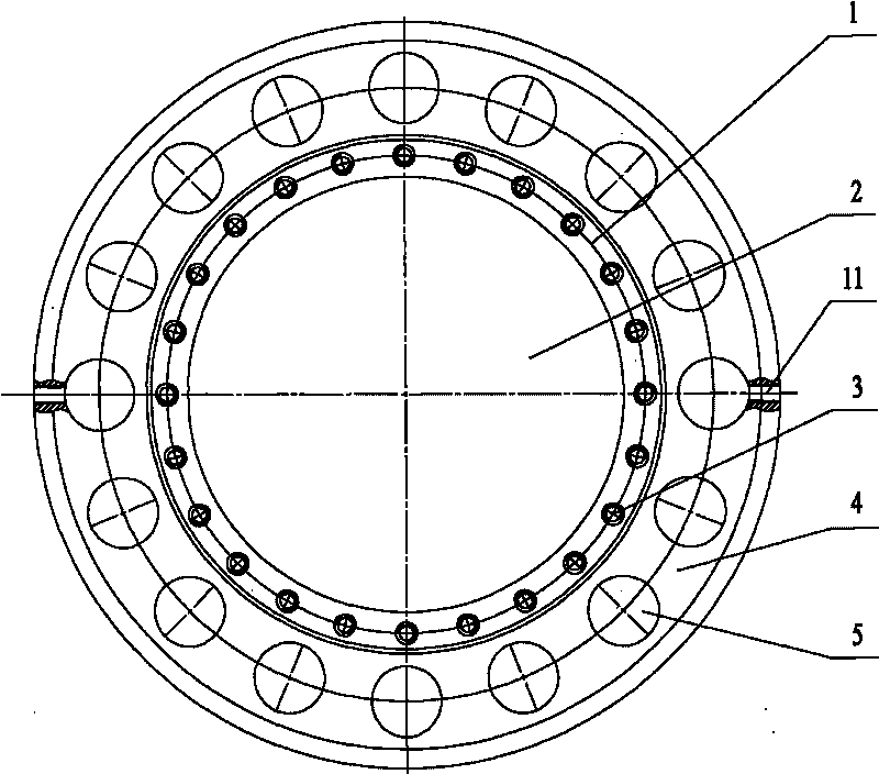
[0027] High-pressure rotor grate disc single disc reaming method, the grate disc 9 is separately fixed on the fixture 10 to ensure that the single disc reaming is carried out under the condition that the axial deformation of the single grate disc 9 is consistent with the assembly state, and the high-pressure rotor grate disc The procedure for reaming a single disc of disc 9 is as follows:

[0028] 1. Assemble the grate toothed disc to be processed on the fixture separately, use a torque wrench and process bolts to press the grate toothed disc through the bolt holes on the grate toothed disc, and the pressing torque is 20N. The amount of deformation is consistent with the assembly state;

[0029] 2. Install the jig equipped with the grate tooth plate on the radial drilling machine, use the dial gauge to align it, so that the plane runout of A surface is ≤0.02mm, and press it with bolts;

[0030] 3. Remove eve...

Embodiment 2

[0037] Embodiment 2: The diameter of the machining hole is 10.8mm

[0038] High-pressure rotor grate disc single disc reaming method, the grate disc 9 is separately fixed on the fixture 10 to ensure that the single disc reaming is carried out under the condition that the axial deformation of the single grate disc 9 is consistent with the assembly state, and the high-pressure rotor grate disc The procedure for reaming a single disc of disc 9 is as follows:

[0039] 1. Assemble the grate toothed disc to be processed on the fixture separately, use a torque wrench and process bolts to press the grate toothed disc through the bolt holes on the grate toothed disc, and the pressing torque is 20N. The amount of deformation is consistent with the assembly state;

[0040] 2. Install the jig equipped with the grate tooth plate on the radial drilling machine, use the dial gauge to align it, so that the plane runout of A surface is ≤0.02mm, and press it with bolts;

[0041] 3. Remove eve...

Embodiment 3

[0048] Embodiment 3: The diameter of the machining hole is 11.1mm

[0049] High-pressure rotor grate disc single disc reaming method, the grate disc 9 is separately fixed on the fixture 10 to ensure that the single disc reaming is carried out under the condition that the axial deformation of the single grate disc 9 is consistent with the assembly state, and the high-pressure rotor grate disc The procedure for reaming a single disc of disc 9 is as follows:

[0050] 1. Assemble the grate toothed disc to be processed on the fixture separately, use a torque wrench and process bolts to press the grate toothed disc through the bolt holes on the grate toothed disc, and the pressing torque is 20N. The amount of deformation is consistent with the assembly state;

[0051] 2. Install the jig equipped with the grate tooth plate on the radial drilling machine, use the dial gauge to align it, so that the plane runout of A surface is ≤0.02mm, and press it with bolts;

[0052] 3. Remove every...


PUM

PropertyMeasurementUnit
Diameter sizeaaaaaaaaaa

Abstract

The invention discloses a single-disk reaming method of a high-pressure rotor labyrinth disk. A labyrinth disk is independently fixed on a clamp to ensure that the single labyrinth disk carries out single disk reaming when axial deformation is coincident to the assembly state; the labyrinth disk to be processed is independently assembled on the clamp and is tightly pressed by process bolts so as to ensure that the axial deformation of the labyrinth disk and the assembly state are coincident; the clamp in which the labyrinth disk is arranged is installed on a rock arm drilling machine, and then the process bolt on the labyrinth disk is removed every other process bolt; according to the size required to be processed, a proper cutter is chosen, installed on the drilling machine and fixed after centering; rough reaming is carried out on the loosened bolt hole of the labyrinth disk, and then fine reaming is carried out; manual feed is adopted for processing; the cutter rotation speed is 70-80 r / min; the process bolts are used for tightly pressing processed holes, other process blots which do not process holes are loosened, and the bolt holes which are not processed are processed; and a dial test indicator and a ring gauge are adopted for aperture measurement detection.

Description

technical field [0001] The invention relates to the field of mechanical processing, in particular to a single disc reaming method for a high-pressure rotor grate tooth disc. Background technique [0002] The positions of the bolt holes of the original high-pressure compressor rotor assembly when replacing the new powder alloy grate disc in a major overhaul machine are inconsistent, and the position of the bolt holes of individual rotor parts is relatively large. When replacing the powder alloy grate disc, high-pressure rotor combined reaming . Combined reaming needs to ream the grate tooth disc and other discs together. This process has the following problems: With the increase of engine repair times, the diameter of the high-pressure rotor bolt hole of some long-life engines has reached Φ10.9 and Φ11. The bolt hole diameter of the high-pressure rotor requires a maximum allowable diameter of Φ11.1, and each time the combined reaming of the high-pressure rotor needs to be in...

Claims


Application Information

Patent Timeline
IPC IPC(8): B23D75/00B23Q3/06B23D77/00
Inventor 孙汕民王洪海吴联合曹锋勇赵健王惠林王辉景巍巍李希顺
Owner SHENYANG LIMING AERO-ENGINE GROUP CORPORATION
Learn More