
Method of joining a thermoplastic material to a fibre composite material

A fiber composite material, thermoplastic material technology, applied in chemical instruments and methods, synthetic resin layered products, household components, etc., can solve problems such as disadvantages

Active Publication Date: 2010-06-09
AIRBUSOPERATIONS有限公司
View PDF1 Cites 13 Cited by
  • Summary
  • Abstract
  • Description
  • Claims
  • Application Information

AI Technical Summary

Problems solved by technology

However, this has the disadvantage that the size and location of the holes for the screws must be known during the manufacture of the plastic bracket and element, and new holes must be added if the attachment position of the element and / or plastic bracket changes
This will be detrimental to the entire production process

Method used


Image

  • Method of joining a thermoplastic material to a fibre composite material
  • Method of joining a thermoplastic material to a fibre composite material
  • Method of joining a thermoplastic material to a fibre composite material

Examples


Embodiment 1

[0050] According to Example 1, a stent comprising a thermoplastic material is shown in Figure 5 In this case, the bracket is bonded to a fiber composite material, which in this embodiment is a fiber reinforced plastic.

[0051] In this embodiment, the bracket 33 comprises a disc-shaped connecting portion 34 which is connected with fiber-reinforced plastic and a seat 35 . The connection part 34 and the support 35 have a polyamide PA66 content of 70% and a glass fiber content of 30%. The stand 35 is used to support objects such as electrical leads or heavier objects. The thickness of the connecting portion is 2.2 mm in this embodiment, and the diameter of the connecting portion is 24 mm in this embodiment.

[0052] In this embodiment the fiber reinforced plastic is a sheet of glass reinforced plastic and the top outer layer of the sheet to which the surface 36 of the bracket 33 will be joined is 40% resin and 60% glass fiber braid. The thickness of the flakes is 2 mm in tota...

Embodiment 2

[0057] In this embodiment, the bracket shown in Embodiment 1 is also used. In this embodiment, the fiber-reinforced plastic is a carbon fiber-reinforced plastic sheet, and the top outer layer of the sheet connected by the bracket is 45% resin and 55% carbon fiber braid. The thickness of the sheet was 2 mm.

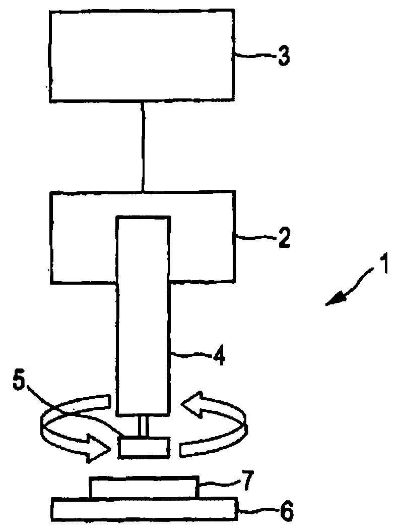
[0058] The method according to the invention for joining thermoplastic material (stent) to fiber reinforced material (carbon fiber reinforced plastic sheet) by using figure 1 The device 1 shown is realized.

[0059] In this embodiment, the angular frequency is 160 Hz and the welding time is 3 seconds. The welding time is the time during which the bracket moves relative to the fibre-reinforced plastic, the predetermined pressure between the thermoplastic material and the fibre-reinforced plastic being 1.0 bar in this example. In this exemplary embodiment, the welding process is regulated by the welding time, ie each welding process is 3 seconds. In these examples, tensi...


PUM

PropertyMeasurementUnit
Thicknessaaaaaaaaaa

Abstract

The invention relates to a method of joining a thermoplastic material (10) to a fibre composite material (11), the thermoplastic material (10) being welded to the fibre composite material (11), wherein the fibre composite material is a fibre- reinforced matrix material or comprises a fibre-reinforced matrix material and wherein the matrix material is a thermoset or comprises a thermoset. Preferably, the thermoplastic material (10) and the fibre composite material (11) are welded together by motion welding and / or by induction welding. In addition, it is preferred that, for the preferred induction welding, an electrically conductive material is arranged in a joint area between the thermoplastic material and the fibre composite material and induction heat is generated in the electrically conductive material which is sufficient to cause the thermoplastic material to start to melt and to heat the fibre composite material.

Description

technical field [0001] The invention relates to a joining method of thermoplastic material and fiber composite material. Furthermore, the invention also relates to a device comprising a thermoplastic material and a fiber composite material. Background technique [0002] In aircraft, the thermoplastic material is usually connected to the fiber composite material by means of mechanical means, for example by means of screws or by means of adhesives. For example, plastic brackets comprising thermoplastic materials are often attached to elements such as side wall panels or hat rack boxes in pressurized areas comprising fiber composite materials, for example in the cabin area of ​​an aircraft. [0003] Bonding between plastic scaffolds containing thermoplastics and components containing fiber composites requires pretreatment of the adhesive surface of the plastic scaffold. These surfaces first need to be roughened and then pre-treated with a primer. Only after pretreatment can ...

Claims


Application Information

Patent Timeline
IPC IPC(8): B29C65/00B29C65/06B29C85/36B32B27/02B32B3/12B64C1/00
CPCB29K2305/00B29L2031/3076B29C66/721B29K2309/08B29C66/72321B29C66/949B29C65/3644B29K2105/14B29K2105/101B29L2031/608B29C65/0672B29C65/3612B29K2101/12B29C65/3656B29C65/3676B29K2105/0845B29C65/06B29C65/36B32B27/04B29L2009/003B29L2009/00B29K2307/00B29C66/7392B29C66/47B29C65/368B29K2077/00B29K2101/10B29C66/727B29C66/8322B29C66/7212B29C66/72143B29C66/71B29C66/7394B29C66/72141B29C66/7254B29C66/73921B29C66/1122B29K2307/04B29K2071/00B29K2079/085B29K2081/06B29K2079/08B29K2069/00B29K2033/12
Inventor 萨宾·沃洛奇约根·申克乔治·华盛戈尔
Owner AIRBUSOPERATIONS有限公司
Learn More