Fast connector

A technology of fast connection and connectors, applied in the field of connectors, can solve problems such as easy to fall off, poor connection effect, long connection time of connectors, etc., and achieve the effect of not easy to fall off and fast connection

Active Publication Date: 2011-08-10
ZHANGJIAGANG UCHEN NEW ENERGY TECH CO LTD
View PDF0 Cites 3 Cited by
  • Summary
  • Abstract
  • Description
  • Claims
  • Application Information

AI Technical Summary

Problems solved by technology

The connection time of the connector with this structure is longer, and the connection effect between the male terminal and the female terminal is not very good, and it is easy to fall off

Method used


Image

  • Fast connector
  • Fast connector
  • Fast connector

Examples


Embodiment Construction

[0014] Specific embodiments of the present invention will be described in detail below in conjunction with the accompanying drawings.

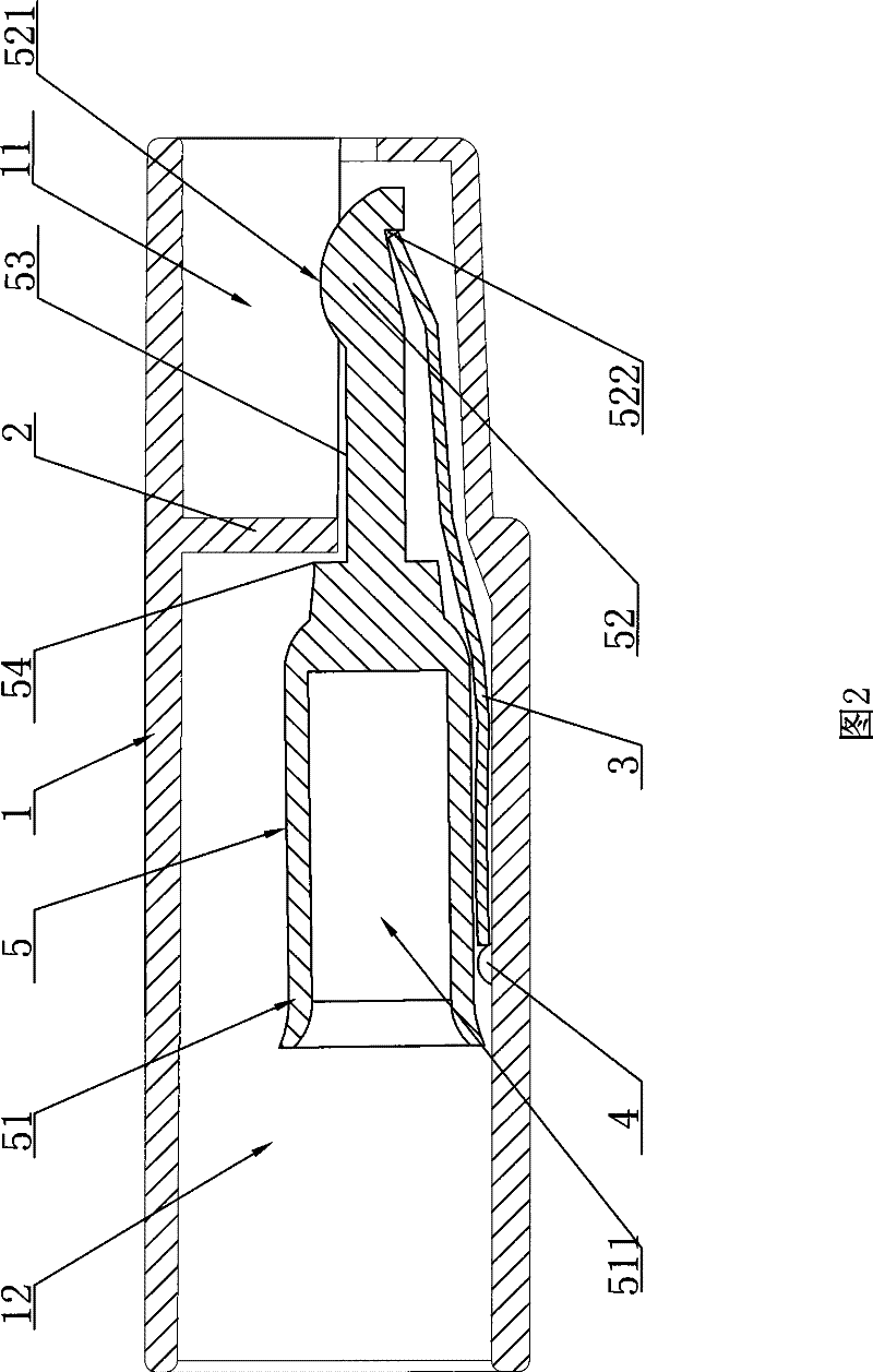
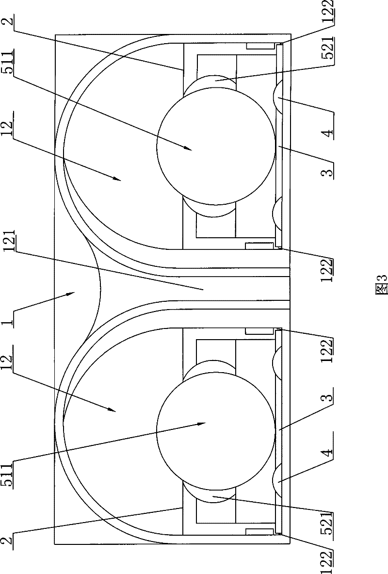
[0015] Such as Figures 1 to 4 As shown, the quick connector includes: a hollow housing 1, a section of diaphragm 2 is arranged on one side of the housing 1 to divide the housing 1 into a front cavity 11 and a rear cavity 12, the housing 1 The front chamber 11 and the rear chamber 12 communicate with each other. A medial septum 121 is arranged in the rear chamber 12 to divide the rear chamber 12 into two parts. A pair of slots 122 are respectively arranged in the rear chamber 12. The slots 122 are located in the casing On both sides of the other side of the interior, one end of the reed 3 is respectively embedded in the two slots 122, and a positioning block 4 is respectively arranged on the inner bottom surface of the rear cavity 12 of the housing 1 to abut against the end of the reed 3 , in this embodiment, two positioning blocks 4 abutting...


PUM


Abstract

The invention discloses a fast connector for fast connection. The fast connector comprises a hollow shell. A section of horizontal partition board for partitioning the inner part of the shell into a front cavity and a rear cavity is arranged on one side on the inner part of the shell; the front cavity and the rear cavity of the shell are mutually communicated; a longitudinal partition board is arranged in the rear cavity to separate the rear cavity into two parts; a pair of insertion grooves are arranged in the rear cavity respectively and positioned on two edge sides in the shell; one end ofone spring leaf and one end of the other spring leaf are inserted in the two insertion grooves respectively; positioning blocks propped against the end parts of the spring leaves are arranged on the inner bottom surface of the shell rear cavity respectively; the other end of each of the spring leaves penetrates through the connecting part between the front cavity and the rear cavity and tilts upwards; a connecting part is arranged between each of the spring leaves and the horizontal partition board; a longitudinal guide block is arranged on one side of the inner wall of the shell front cavity; and a longitudinal guide groove is arranged on the outer wall of the shell front cavity. The fast connector has the advantages that the fast connector with the structure enables the connection to befast and accurate, and the falling phenomenon between connecting terminals is prevented.

Description

technical field [0001] The invention relates to a connection head, in particular to a connection head used for connection between an input line of an electrical device and an external power supply wire. Background technique [0002] The existing connector used for connecting the input line of electrical equipment and the external power supply wire is mainly composed of a male joint and a female joint. The outer shell of the male joint is provided with threads, and the outer shell of the female joint is provided with threaded joints. The nuts that cooperate with each other are provided with male terminals in the shell of the male joint, and are provided with female terminals that cooperate with the male terminals in the shell of the female joint. The connection time of the connector with this structure is relatively long, and the connection effect between the male terminal and the female terminal is not very good, and it is easy to fall off. Contents of the invention [00...

Claims


Application Information

Patent Timeline
Patent Type & Authority Patents(China)
IPC IPC(8): H01R13/20H01R13/627
Inventor 陈建刚郑晓波
Owner ZHANGJIAGANG UCHEN NEW ENERGY TECH CO LTD
Why Eureka
Try Eureka