
High-temperature fume furnace of circulating fluidized bed and control method thereof

A circulating fluidized bed, high-temperature flue gas technology, applied in the field of flue gas furnaces, can solve the problems of uneven air distribution, low fluidization gas velocity, affecting combustion efficiency and flue gas quality, etc., so as to improve combustion efficiency and strengthen airflow. The effect of stirring and avoiding coking in the furnace

Active Publication Date: 2012-07-25
CHNA ENERGY INVESTMENT CORP LTD +3
View PDF0 Cites 0 Cited by
  • Summary
  • Abstract
  • Description
  • Claims
  • Application Information

AI Technical Summary

Problems solved by technology

Taking the ordinary fluidized bed flue gas furnace in the prior art as an example, on the one hand, the fluidized bed flue gas furnace is prone to local failure of normal fluidization due to low fluidization gas velocity and uneven air distribution, resulting in the problem of "dead bed" ; Therefore, the capacity of the fluidized bed flue gas furnace is generally below 20MW, and it is difficult to increase the capacity
On the other hand, there are a large amount of coal ash and unburned fine carbon particles in the generated flue gas, which affects the combustion efficiency and flue gas quality
At the same time, the furnace wall of the fluidized bed flue gas furnace also has disadvantages such as easy bulge, crack and collapse.
[0003] In addition, the above-mentioned fluidized bed flue gas furnace usually uses a high excess air coefficient to control the temperature of the flue gas at the outlet, so the oxygen content of the flue gas at the outlet is relatively high, and it will be dangerous when used for drying flammable and explosive materials.

Method used


Image

  • High-temperature fume furnace of circulating fluidized bed and control method thereof
  • High-temperature fume furnace of circulating fluidized bed and control method thereof
  • High-temperature fume furnace of circulating fluidized bed and control method thereof

Examples


Embodiment Construction

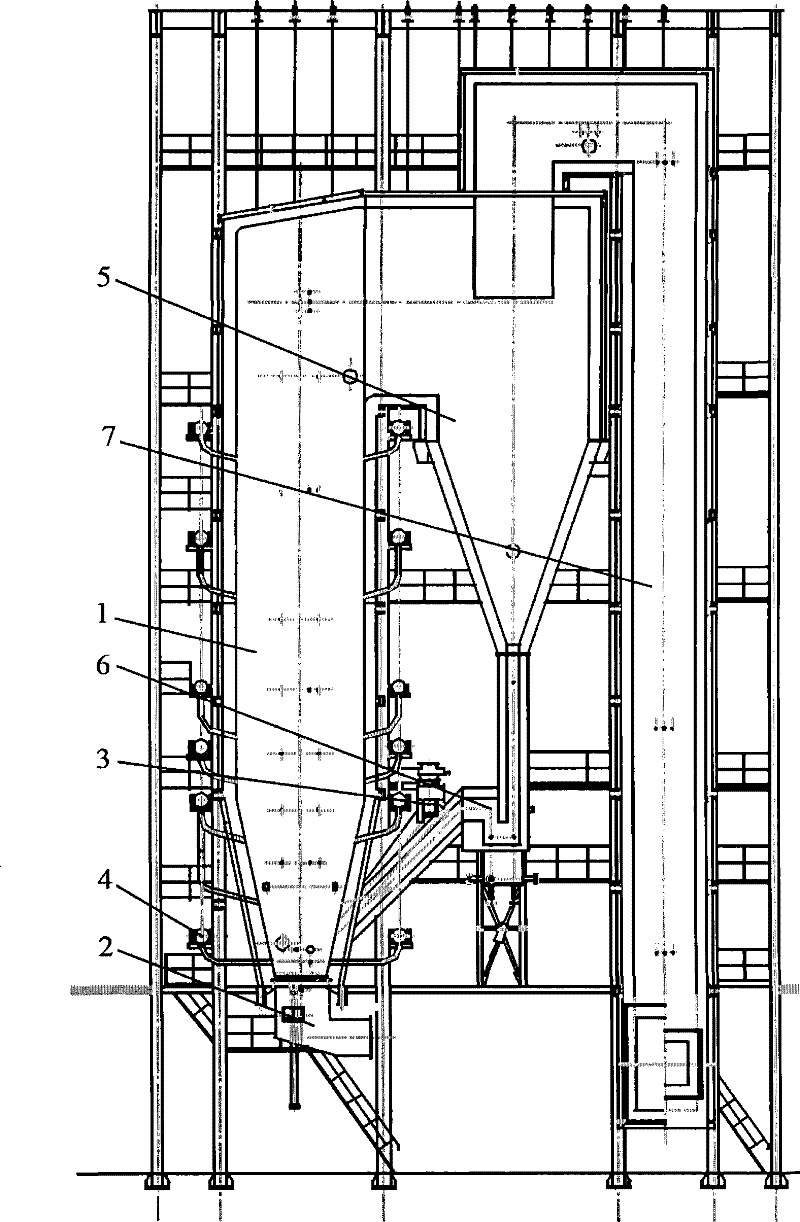
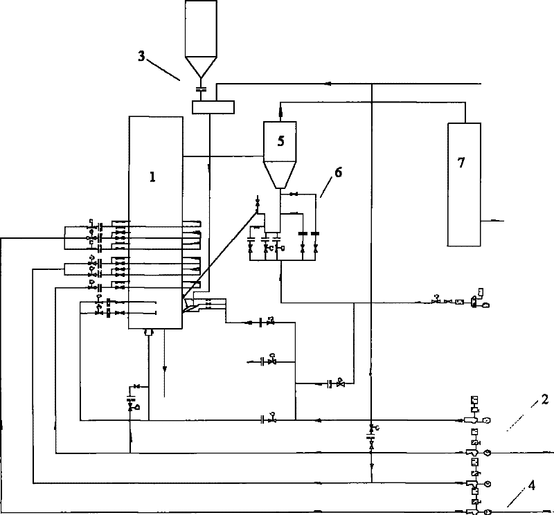
[0020] Such as figure 1 As shown, the circulating fluidized bed high-temperature flue gas furnace of the present invention includes a furnace 1, an air distribution device 2, a pneumatic coal sowing device 3, a secondary air and inert gas device 4, a cyclone separator 5, a feeding device 6 and a tail smoke Road 7. figure 2 It represents the control structure of the circulating fluidized bed high-temperature flue gas furnace of the present invention.

[0021] The air distribution device 2 includes components such as an air distribution plate, an air cap, and an air chamber. The air cap and the air distribution plate are installed in an equal-pressure air chamber, and the gas from a gas source (such as a fan) is introduced into the air chamber through the air cap arranged on the air distribution plate. , making coal fluidized combustion. The air outlet of the air distribution device 2 communicates with the furnace. The pneumatic coal sowing device 3 can be realized by a blow...


PUM


Abstract

This invention discloses a high-temperature fume furnace of a circulating fluidized bed. The fume furnace comprises a hearth, an air distributor, a pneumatic spreader stroker, a secondary air and inert gas device, a cyclone separator, a feedback unit and a tail flue, wherein the outlet of the air distributor and the spreading opening of the pneumatic spreader stroker are both connected with the hearth; the secondary air and inert gas device is also communicated with the hearth; the outlet of the hearth is connected with the inlet of the cyclone separator; one end of the feedback unit is connected with the solid outlet of the cyclone separator, while the other end thereof is communicated with the hearth; and the tail flue is connected with the gas outlet of the cyclone separator. The high-temperature fume furnace of the circulating fluidized bed of the invention can improve the combustion efficiency and the capacity of the fume furnace, control the combustion temperature of the health,prevent coking in the hearth, and keep the oxygen content of the gas of below 8 percent at the outlet.

Description

technical field [0001] The invention relates to a flue gas furnace, in particular to a circulating fluidized bed high temperature flue gas furnace and a control method thereof. Background technique [0002] Flue gas furnaces are widely used in drying, calcination and other operations in industrial production. Taking the ordinary fluidized bed flue gas furnace in the prior art as an example, on the one hand, the fluidized bed flue gas furnace is prone to local failure of normal fluidization due to low fluidization gas velocity and uneven air distribution, resulting in the problem of "dead bed" ; Therefore, the capacity of the fluidized bed flue gas furnace is generally below 20MW, and it is difficult to increase the capacity. On the other hand, there are a large amount of coal ash and unburned fine carbon particles in the generated flue gas, which affects the combustion efficiency and flue gas quality. At the same time, the furnace wall of the fluidized bed flue gas furnace...

Claims


Application Information

Patent Timeline
Patent Type & Authority Patents(China)
IPC IPC(8): F23C10/02F23C10/18F23C10/28
Inventor 邵俊杰万思本苏晓辉陈金火张平何立新田天夏树根
Owner CHNA ENERGY INVESTMENT CORP LTD
Learn More