
Combined butterfly valve

A combination and butterfly valve technology, applied in the direction of lifting valve, valve details, valve device, etc., can solve problems such as troublesome, difficult to guarantee the reserved length and size of the pipeline, and difficult to guarantee the quality

Inactive Publication Date: 2010-06-09
杨世奉
View PDF0 Cites 2 Cited by
  • Summary
  • Abstract
  • Description
  • Claims
  • Application Information

AI Technical Summary

Problems solved by technology

However, when installing or replacing butterfly valves with standard structural lengths during use, it is difficult to ensure the size of the reserved length of the pipeline, which brings difficulties to the installation. It is often necessary to use telescopic tubes to adjust the connection, but the telescopic tubes often lose their telescopic function due to corrosion. , it is difficult to remove the butterfly valve during maintenance
In the current implementation 2, a connecting wheel is often placed in the butterfly valve well to replace the telescopic tube. When repairing and replacing the butterfly valve, the lead opening of the connecting wheel has to be baked by gas welding, and the butterfly valve is removed after removing the connecting wheel, which increases the difficulty of replacing the butterfly valve.
In addition, when the butterfly valve is installed at the end of the movable (freely moving) pipe, in addition to the butterfly valve, a joint is also required to connect with the pipe or the reservoir interface, so that the two can be closely matched so that the two can be quickly connected. At present, the butterfly valve , the joint connection components need to be purchased separately and combined again. On the one hand, it is difficult to purchase the supporting components at the same time, which brings inconvenience to the work. Trouble, affecting work efficiency

Method used


Image

  • Combined butterfly valve
  • Combined butterfly valve

Examples


Embodiment Construction

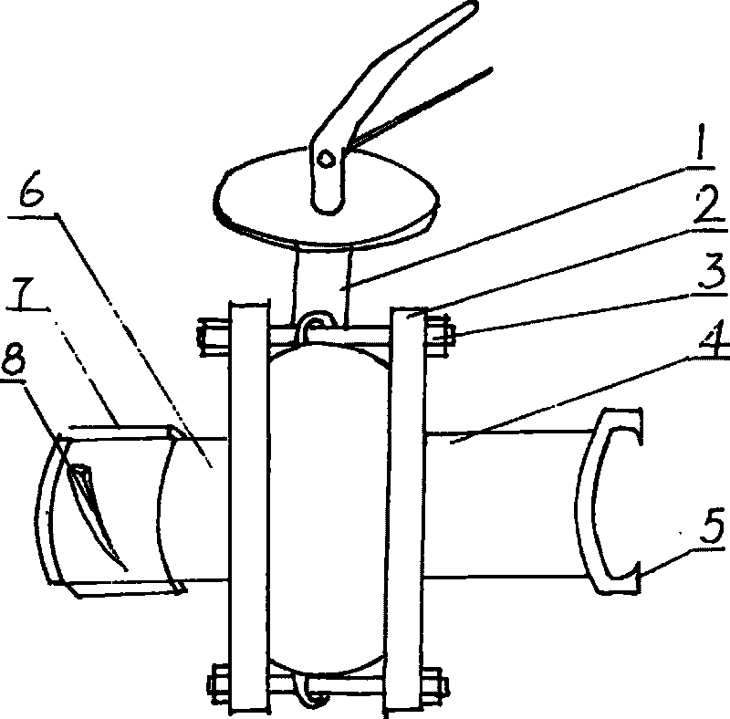
[0010] Such as figure 1 As shown, the present invention includes a butterfly valve body 1 and joints 4, 6. A flange 2 is provided on both sides of the butterfly valve body, and one side of the flange is fixedly connected to the joint. The joint is set according to needs and can be a male joint. 4. It can also be a female connector 6. The said male joint is fixedly connected with cat claws 5 on the outer end surface of the short tube, and the number of cat claws is determined according to the needs, which are generally arranged symmetrically, and can also be arranged equidistantly. In this embodiment, two symmetrical arrangements are selected, and the said The female joint of the short pipe is provided with an "O" type seal ring groove at the outer end of the short pipe, so as to be plugged with the seal ring, and a differential sliding sleeve 7 is set on the short pipe. There are spiral protrusions 8 on the outside of the differential sliding sleeve. The spiral protrusions ca...


PUM


Abstract

The invention discloses a combined butterfly valve, comprising a butterfly valve body (1) and joints (4) and (6). The butterfly valve is characterized in that two sides of the butterfly valve body (1) are respectively provided with a flange (2); one side of each flange is fixedly connected with the joint, while the other side is fixedly connected with the butterfly valve into a whole by using a bolt (3) through a screw hole on the flange and a screw hole on the butterfly valve. The combined butterfly valve is convenient in quick mounting, quick detaching and maintaining for the butterfly valve, as the butterfly valve and the two joints are connected into a whole through the bolts and the flanges.

Description

technical field [0001] The invention relates to a cut-off device with a closing element, in particular to a combined butterfly valve. Background technique [0002] As we all know, the butterfly valve has the advantages of small size, simple structure, small flow resistance, small opening and closing torque, flexible operation, ability to cut off, adjust flow and store multiple advantages, and is widely used in the middle or end of pipes to control fluid flow. However, when installing or replacing butterfly valves with standard structural lengths during use, it is difficult to ensure the size of the reserved length of the pipeline, which brings difficulties to the installation. It is often necessary to use telescopic tubes to adjust the connection, but the telescopic tubes often lose their telescopic function due to corrosion. , It is difficult to remove the butterfly valve during maintenance. In the current implementation 2, a connecting wheel is often placed in the butterf...

Claims


Application Information

Patent Timeline
Patent Type & Authority Applications(China)
IPC IPC(8): F16K1/22F16K27/02
Inventor 杨世奉
Owner 杨世奉
Learn More