
Multifunction drawer type soldering iron wiping stand

A drawer-type, multi-functional technology, applied in auxiliary devices, metal processing equipment, manufacturing tools, etc., can solve the problems of serious hidden dangers in solder quality, inconvenient maintenance, and lack of time, so as to facilitate production line operations, installation and use, and convenience cleaning effect

Active Publication Date: 2013-06-05
DELTA ELECTRONICS DONGGUAN +1
View PDF2 Cites 0 Cited by
  • Summary
  • Abstract
  • Description
  • Claims
  • Application Information

AI Technical Summary

Problems solved by technology

[0003] The current practice is: the workers in the factory rest on average every 2 hours. They usually use this time to rinse the foam and squeeze out the excess water with their hands. However, the time for this operation is usually less than 2 hours. If you wipe frequently, the foam will dry out. In order to avoid this situation, the operator often adds too much water to the foam. At this time, there are potential hidden dangers in the solder quality, and the following disadvantages exist:
[0004] 1. Squeezing foam by hand cannot guarantee the standardization of its water content, and there are serious hidden dangers in the quality of solder;
[0005] 2. The operator has no time to add water to the foam;
[0006] 3. The foam needs to be washed with running water, wasting water resources;
[0007] 4. The soldering iron stand is an integral structure, which is easy to get dirty and difficult to maintain, which brings inconvenience to maintenance

Method used


Image

  • Multifunction drawer type soldering iron wiping stand
  • Multifunction drawer type soldering iron wiping stand
  • Multifunction drawer type soldering iron wiping stand

Examples


Embodiment Construction

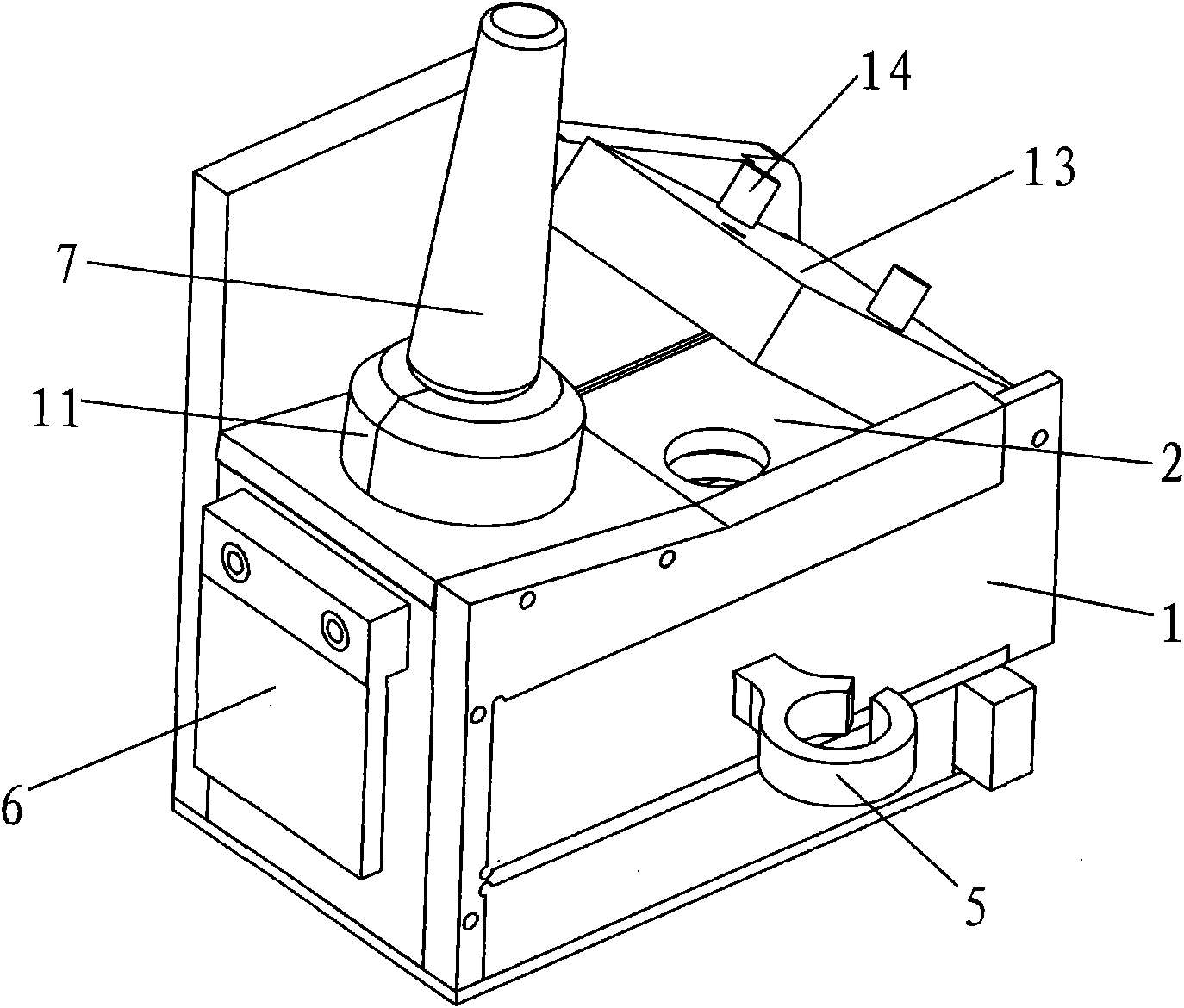
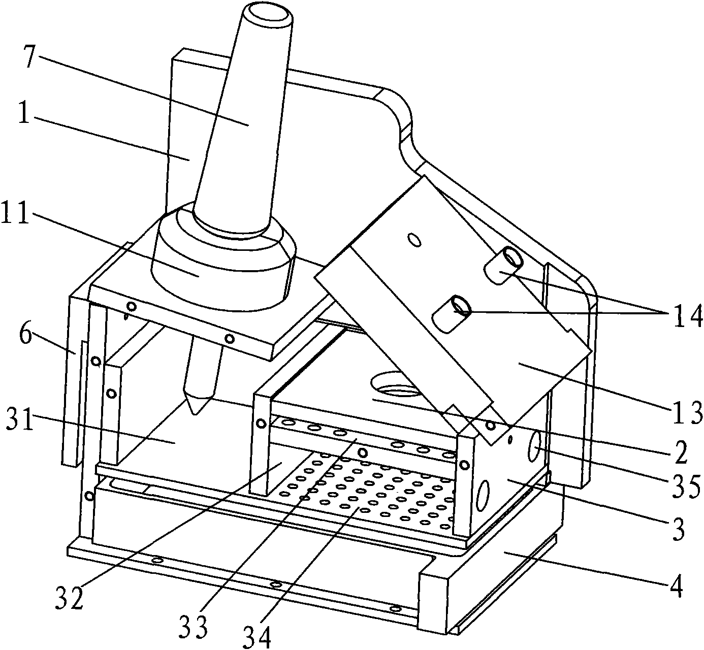
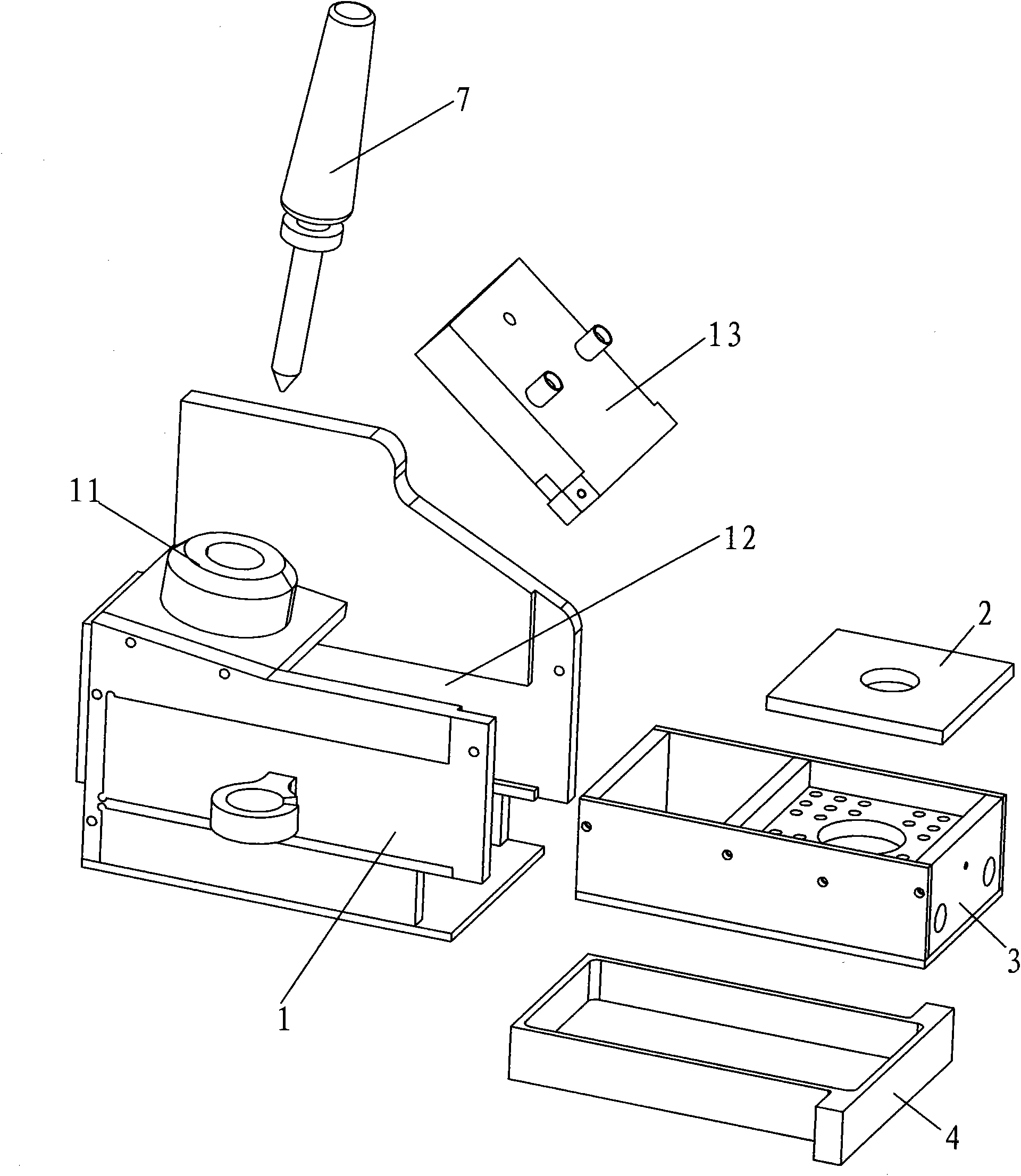
[0026] Below in conjunction with accompanying drawing, the present invention will be further described, see Figure 1~3 As shown, the present invention includes a frame 1, a tin slag box 3, a water container 4 and a water-absorbing foam 2. The upper end surface of the frame 1 is provided with a soldering iron placement port 11 for inserting a soldering iron 7. The frame 1 is from top to bottom. The slag box 3 and the water box 4 can be drawn out along the front end of the frame 1 by sliding down. The slag box 3 and the water box 4 form a drawer structure in the frame 1, and the water-absorbing foam 2 is arranged in the slag box 3 middle.

[0027] Frame 1 is an upper and lower double-layer drawer structure, and the right wall is higher than the soldering iron placement port 11, which is designed for protection to avoid scalding surrounding objects and personnel. The left side of the frame 1 is provided with a power cord hook 5 for clamping the soldering iron power cord. The po...


PUM


Abstract

The invention relates to the technical field of soldering iron stands, in particular to a multifunction drawer type soldering iron wiping stand. The stand comprises a frame and an absorbent foam. A soldering iron placing hole is arranged on the upper end face of the frame. A solder splash box and a water containing box, which can be drawn out along the front end of the frame, are glidingly arranged in the frame from top to bottom and are of drawer type structure in the frame. The absorbent foam is arranged in the solder splash box. The soldering iron is inserted from the soldering iron placing hole under the non-working state. The soldering iron tips are arranged in the solder splash box. After the soldering iron is wiped on the absorbent foam under the working state, the solder splash falls into the solder splash box and the redundant left water on the absorbent foam flows into the water containing box. The stand is of composite structure, can recycle the left water, save the water resources, standardize the water content in the absorbent foam, improve the soldering tin quality and be widely applied to tin soldering sites, has multiple functions and is convenient to use, install and clean, easy to maintain and convenient for production line operation.

Description

Technical field: [0001] The invention relates to the technical field of soldering iron stands, in particular to a multifunctional drawer-type soldering iron wiping stand. Background technique: [0002] When soldering, the tip of the soldering iron must be wiped on the water-containing foam for 2 to 3 times to remove oxides on the tip of the soldering iron and facilitate soldering. If the foam is too dry, the high-temperature soldering iron tip will scald the foam, resulting in frequent replacement of foam on the production line; The product has bad phenomena such as cold welding and virtual welding. [0003] The current practice is: the workers in the factory rest on average every 2 hours. They usually use this time to rinse the foam and squeeze out the excess water with their hands. However, the time for this operation is usually less than 2 hours. If you wipe frequently, the foam will dry out. In order to avoid this situation, the operator often adds too much water to th...

Claims


Application Information

Patent Timeline
Patent Type & Authority Patents(China)
IPC IPC(8): B23K3/08
Inventor 刘斌张向东
Owner DELTA ELECTRONICS DONGGUAN
Learn More