Paper chopping blade and machining method thereof

A processing method and technology of blades, which are applied to knives, grain processing, household appliances, etc., can solve the problems of cumbersome processing of shredder blades, poor assembly precision of paper shredder knives, and high cost of energy strip steel, and achieve low cost and small size. Precise, productive results

Active Publication Date: 2010-06-09
DONGGUAN ELITE ELECTRIC HARDWARE PRODUCT CO LTD
View PDF0 Cites 11 Cited by
  • Summary
  • Abstract
  • Description
  • Claims
  • Application Information

AI Technical Summary

Problems solved by technology

However, the finish rolling of strip steel consumes a lot of energy and the cost of finished strip steel is relatively high; in addition, there is generally a thickness tolerance of 0.03-0.05mm in the finish rolled steel strip, because a cutter is usually equipped with about 60 pieces of shredded paper In this way, the cumulative thickness tolerance of the cutter reaches 1.8-3mm, resulting in poor assembly accuracy of the shredder cutter, which in turn affects the shredding effect. Therefore, it is necessary to finish the strip steel after finishing rolling and process it into shredded paper The required thickness of the blade, which leads to cumbersome processing procedures, high energy consumption and low production efficiency of the shredding blade

Method used


Image

  • Paper chopping blade and machining method thereof
  • Paper chopping blade and machining method thereof
  • Paper chopping blade and machining method thereof

Examples


Embodiment Construction

[0021] Embodiments of the present invention will now be described with reference to the drawings, in which like reference numerals represent like elements.

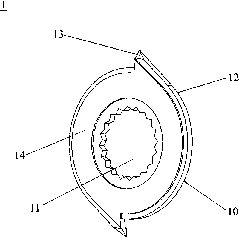
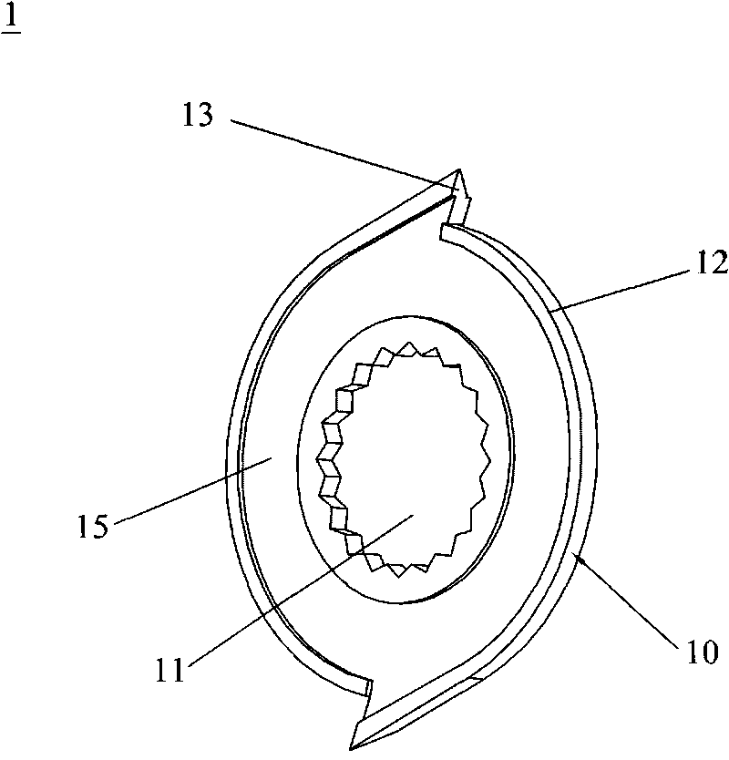
[0022] refer to Figure 1-2 , is a perspective view of a shredding blade 1 produced by the processing method of the shredding blade of the present invention, the shredding blade 1 includes a blade body 10, an installation hole 11 in the center of the blade body 10, a knife edge positioned at the periphery of the blade body 12 and a knife tip 13 protruding outward from the periphery of the knife body, the area between the knife edge 12 and the mounting hole 11 on the outer surface of the knife body 10 is provided with a concave ring 14, and the outer surface of the other side of the knife body 10 The area between the knife edge 12 and the mounting hole 11 is correspondingly provided with a protruding ring 15 .

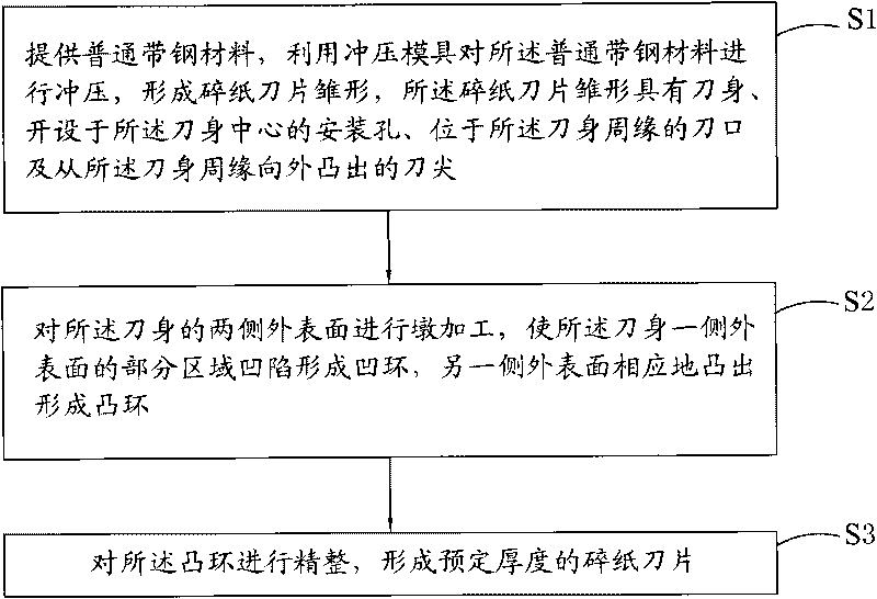
[0023] refer to image 3 , the processing method of shredder blade 1 of the present invention, comprises the f...


PUM


Abstract

The invention discloses a machining method of a paper chopping blade, which comprises the following steps of: (1) providing a common strip steel material, and stamping the common strip steel material by utilizing a stamping die to form a prototype of the paper chopping blade, wherein the prototype of the paper chopping blade is provided with a blade body, an installing hole formed at the center of the blade body, a blade edge positioned at the periphery of the blade body and a blade tip which protrudes outward from the periphery of the blade body; (2) tamping the outer surfaces of two sides of the blade body so that the partial region of the outer surface of one side of the blade body sags to form a concave ring, and the outer surface of the other side correspondingly protrudes to form a convex ring; and (3) finishing the convex ring to form the paper chopping blade with the preset thickness. The machining method of the paper chopping blade of the invention can be used for producing a paper chopping blade with a precise size without finely machining the strip steel which is finely rolled, thereby having simple machining processes, small machining energy consumption, low cost, high production efficiency and wide material sources. The invention simultaneously discloses the paper chopping blade produced by the machining method.

Description

technical field [0001] The invention relates to a blade, in particular to a shredding blade and a processing method thereof. Background technique [0002] In the corporate office, many used and discarded papers, because the information recorded on them are corporate secrets, in order to prevent others from obtaining the information recorded on the documents, the paper needs to be shredded, so the paper shredder came into being. Existing paper shredders, whether electric or manual, use their shredding blades to cut waste paper into slender strips or shreds. Generally, the shredding blades are roughly round or bowl-shaped, and they are grouped together. The ground is fixed on two parallel and relatively movable cutter shafts. When the cutter shafts rotate, the paper passing between the shredding blades is cut into thin paper strips or shreds under the extrusion of the shredding blades. The shredding ability of a shredder is generally measured by the maximum number of papers t...

Claims


Application Information

Patent Timeline
Patent Type & Authority Applications(China)
IPC IPC(8): B21D53/64B02C18/18
Inventor 陆学中
Owner DONGGUAN ELITE ELECTRIC HARDWARE PRODUCT CO LTD
Why Eureka
Try Eureka