Device for rotating multi-shuttle box

A technology of shuttle box and hollow rotating shaft, which is applied in the direction of textile, textile, papermaking, loom, etc., can solve the problems affecting the inner quality and appearance of the fabric, destroying the structural integrity of the tubular fabric, etc., and achieve easy replacement of the turntable and realization of various and avoid the effect of twisting

Inactive Publication Date: 2010-06-02
DONGHUA UNIV
View PDF0 Cites 3 Cited by
  • Summary
  • Abstract
  • Description
  • Claims
  • Application Information

AI Technical Summary

Problems solved by technology

However, when the lift-type multi-shuttle box exchanges weft insertion, the relative positions of different shuttles on the same plane do not change, so that the weft yarns cross in the same plane, such as Figure 5 As shown, it is the working diagram of the traditional multi-shuttle box mechanism. The intersection between the first shuttle movement path 23 and the second shuttle movement path 24 is the twisting point 22, which causes the weft yarn twisting phenomenon to occur at the side flange of the multi-shuttle box. , which destroys the integrity of the tubular fabric structure, and ultimately affects the intrinsic quality and appearance of the fabric

Method used


Image

  • Device for rotating multi-shuttle box
  • Device for rotating multi-shuttle box
  • Device for rotating multi-shuttle box

Examples


Embodiment

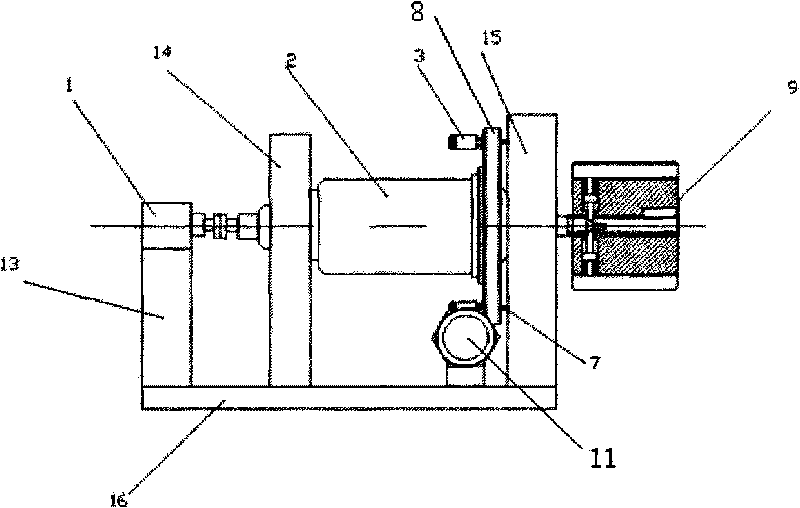
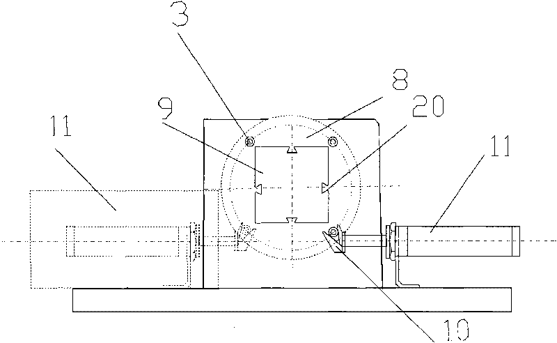
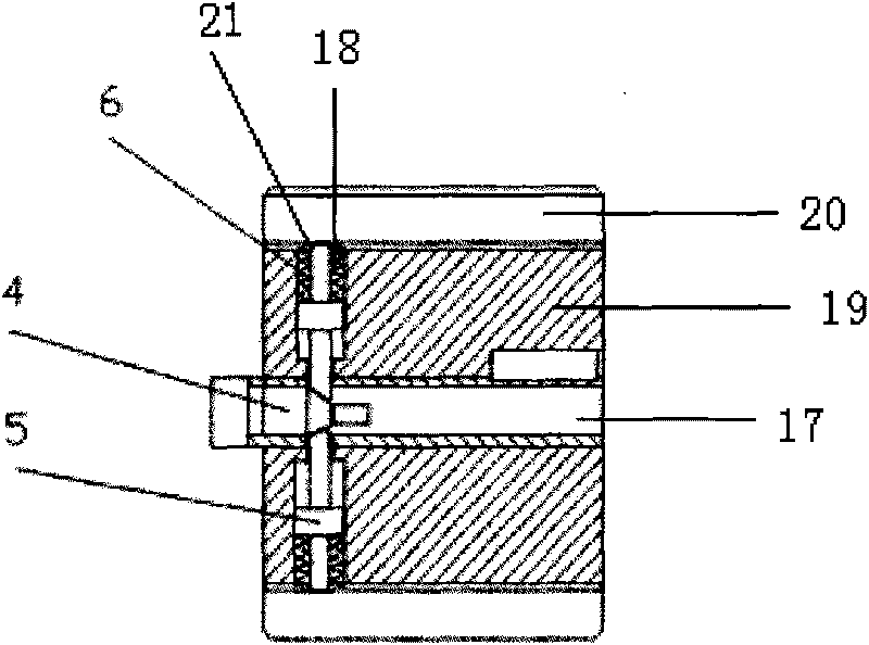
[0022] like figure 1 As shown, it is a structural diagram of the rotary multi-shuttle device, and the rotary multi-shuttle device is composed of a first cylinder 1, a hollow rotating shaft 2, a roller 3, a push rod shaft 4, a lock rod 5, a compression spring 6, and a turntable positioning Component 7, turntable 8, multi-shuttle box 9, push foot 10, second cylinder 11, first bracket 13, second bracket 14, third bracket 15, base 16, axial hole 17, radial hole 18, main body 19 , Shuttle box 20 and shuttle locking hole 21 are formed.

[0023] The base 16 is fixed on the weft insertion side of the loom, and the base 16 is successively provided with a first support 13, a second support 14 and a third support 15 parallel to each other; the first support 13, the second support 14, the third support 15 and the base 16 Use ordinary carbon steel Q235B (GB221-2000) or aluminum alloy ZL102 (GB / T1173-1995)

[0024] Fix the first cylinder 1 with screws on the first bracket 13, the first c...


PUM


Abstract

The invention provides a device for rotating a multi-shuttle box, which is characterized in that a base is provided with a first bracket, a second bracket and a third bracket; the first bracket is provided with a first air cylinder which is connected with a hollow rotating shaft; the hollow rotating shaft is arranged on the second bracket and the third bracket and connected with a turntable and the multi-shuttle box; one side of the turntable is provided with rolling wheels which are uniformly distributed on the outer edge of the turntable; the rolling wheels are connected with a second air cylinder through push pins; the other side of the turntable is provided with a turntable positioning element; the multi-shuttle box comprises a main body and a shuttle box arranged on the external side of the main body; the connecting surface of the main body and the shuttle box is provided with a shuttle locking hole; a push rod shaft which is connected with the hollow rotating shaft is arranged in an axial hole inside the main body; a lock shuttle rod is arranged in a radial hole; one end of the lock shuttle rod abuts on the push rod shaft and the other end is arranged at the shuttle locking hole; and a compression spring is arranged between the lock shuttle rod and the connecting surface of the main body and the shuttle box. The invention can ensure the parallel relationship of two strings of weft all the time, thereby avoiding the twist phenomenon.

Description

technical field [0001] The invention relates to a rotary multi-shuttle box device, which belongs to the field of textile weft insertion mechanisms. Background technique [0002] At present, my country's patent information system shows that there are patents that can realize the weaving of thin, extra-high-density straight tubes and bifurcated tubes on ordinary two-dimensional looms, such as: "Method for introducing continuous weft yarns into rigid rapiers" with application number 200710036884, 200710042827 "Rigid Rapier Loom 1×4 Multi-shuttle Mechanism" and 200810032648's "Rigid Rapier Loom 1×8 Multi-shuttle Mechanism". Among them, the latter two patents adopt the lifting multi-shuttle box, which can continuously and independently introduce multiple weft yarns, and also improve the precision of the loom. However, when the lift-type multi-shuttle box exchanges weft insertion, the relative positions of different shuttles on the same plane do not change, so that the weft yarns ...

Claims


Application Information

Patent Timeline
Patent Type & Authority Applications(China)
IPC IPC(8): D03D43/06
Inventor 李毓陵杨夫全
Owner DONGHUA UNIV
Why Eureka
Try Eureka