
Spherical plain bearing

A sliding bearing, spherical technology, applied in the direction of bearing, bearing assembly, bearing components, etc., can solve the problem of vibration damping and other problems, achieve effective vibration damping, increase driving comfort, and isolate noise.

Inactive Publication Date: 2010-05-26
SAINT GOBAIN PERFORMANCE PLASTICS CORP
View PDF0 Cites 17 Cited by
  • Summary
  • Abstract
  • Description
  • Claims
  • Application Information

AI Technical Summary

Problems solved by technology

However, despite the use of elastomers, such spherical plain bearings still do not achieve satisfactory vibration damping

Method used


Image

  • Spherical plain bearing
  • Spherical plain bearing
  • Spherical plain bearing

Examples


Embodiment Construction

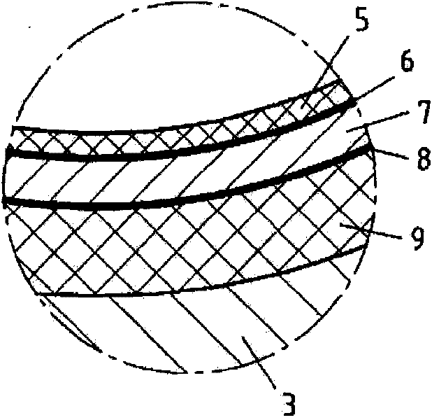
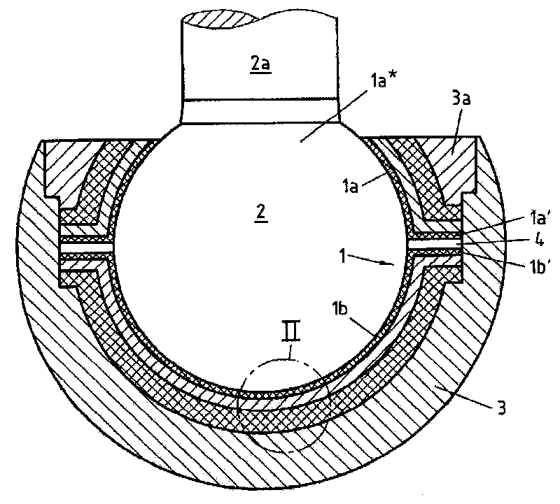
[0022] as in figure 1 The ball and socket joint according to the invention shown in , comprises a self-lubricating spherical plain bearing 1 and a ball joint 2 which is mounted without play in the spherical plain bearing 1 and on which a bearing pin 2a is integrally formed. The spherical plain bearing 1 is mounted in a bearing housing 3 and is held in this position by a ring element 3 a which is an integral part of the bearing housing 3 .

[0023]The spherical plain bearing 1 comprises two spherical plain bearing housings 1a, 1b, the upper plain bearing housing 1a comprising a central opening 1a* through which a bearing pin 2a integrally formed on a ball joint 2 projects out of the socket outside the festival. The opening 1 a * is dimensioned in such a way as to allow the desired movement of the bearing pin 2 a relative to the spherical plain bearing 1 . The two plain bearing shells 1a, 1b each have an annular, radially outwardly directed collar 1a', 1b' on their mutually op...


PUM


Abstract

The invention relates to a spherical plain bearing (1), particularly for a ball and socket joint, with a slide bearing half-liner (1a, 1b), wherein the slide bearing half-liner (1a, 1b) comprises a sliding layer (5) containing a lubricant and at least one dimensionally stable support layer (7). According to the invention, the spherical plain bearing (1) is characterized in that the slide bearing half-liner (1a, 1b) comprises at least one elastic layer (9). The invention further comprises a ball and socket joint comprising a ball-shaped pivot head (2) and a spherical plain bearing (1), and an advantageous use of the spherical plain bearing (1) according to the invention.

Description

technical field [0001] The invention relates to a spherical plain bearing, in particular for a ball and socket joint, having a plain bearing housing, wherein the plain bearing housing comprises a sliding layer comprising a sliding material and at least one dimensionally stable support layer . Background technique [0002] Spherical plain bearings of the type mentioned in the introduction have been known for a long time from the prior art. They are used in particular in ball and socket joints which are used in a very wide range of mechanical engineering fields and in particular in motor vehicle engineering in the form of connecting parts for chassis and steering subassemblies. The housing of the plain bearing is mounted in a bearing housing and surrounds a ball joint integrally formed on the connecting pin. In principle, this geometry allows a rotational movement of the connecting pin in all spatial directions. [0003] In a motor vehicle chassis of conventional design, fo...

Claims


Application Information

Patent Timeline
IPC IPC(8): F16C11/06C09J127/12
CPCF16C33/201F16C2208/82F16C33/206F16C33/28F16C11/083F16C2326/05F16C11/0633F16C2208/10F16C33/203F16C2208/58F16C2226/40F16C2240/60Y10T403/32631F16C11/06C09J127/12
Inventor A·马库斯
Owner SAINT GOBAIN PERFORMANCE PLASTICS CORP
Learn More