
Device for Measuring Tooth Geometry

A geometric shape and geometric figure technology, applied in the field of optical measurement devices, can solve the problems of reducing the digital image resolution of teeth, highly blurred digital images of teeth, and uncertainty of digital image data, so as to improve measurement sensitivity and accuracy, Avoid shadows, effects of high mesh geometry image resolution

Inactive Publication Date: 2011-12-14
宁波思达利光电科技有限公司
View PDF0 Cites 1 Cited by
  • Summary
  • Abstract
  • Description
  • Claims
  • Application Information

AI Technical Summary

Problems solved by technology

This device can provide CAD / CAM (Computer Aided Design, Computer Aided Design / Computer Aided Manufacturing, Computer Aided Manufacturing) processing digital image data that must be used for tooth reconstruction without having to make a tooth model, but this device exists Obvious disadvantages: a) due to the coherence of light, the phase-shift analysis technique using sinusoidal gratings is severely limited by the speckle situation, resulting in a high degree of blurring of the digital image of the teeth; b) the device reduces or eliminates the The background noise and intensity disturbance of linear stripes are reduced, but at the same time, the resolution of digital images of teeth is greatly reduced; c) Phase shift analysis technology is applied to fixed parallel grids, when the height of teeth changes suddenly (greater than 2π difference) It will cause the linear fringe shift to be larger than the grid distance, and more projections or changing the grid distance are required to compensate for this defect, which makes the structure of the device more complicated and causes uncertainty in digital image data
[0004] In addition to the above-mentioned shortcomings, optical measurement devices including the above-mentioned CEREC device have common defects. Since the parallax angle is a very important parameter, the larger the parallax angle is, the higher the sensitivity of the measurement is, but at the same time the shadow problem is more serious , in order to eliminate the shadow as much as possible, the optical measurement device usually chooses a parallax angle less than 10°, or even smaller, but this greatly reduces the measurement accuracy of teeth

Method used


Image

  • Device for Measuring Tooth Geometry
  • Device for Measuring Tooth Geometry
  • Device for Measuring Tooth Geometry

Examples


Embodiment 1

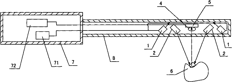
[0017] Embodiment one: if figure 1 As shown, a device for measuring the geometric shape of teeth, the device includes a handle 7 and a probe 8 connected to the handle 7, the probe 8 is provided with two mirror-symmetric light sources 1, two mirror-symmetric projection heads and a set In the imaging unit between the two projection heads, the projection head includes a gradient projection lens 2, and the gradient projection lens 2 is provided with a mesh geometric figure image, and the imaging unit includes a camera 5 and an imaging lens 4, and the camera 5 and the imaging lens 4 are located on the gradient Between the projection lenses 2, the handle 7 is provided with a power supply circuit 71 connected to the light source 1 and an image processing circuit 72 connected to the imaging unit; the incident light emitted by the light source 1 is irradiated on the internal reflection surface of the probe 8, and the incident light passes through the probe The internal reflection surfa...

Embodiment 2

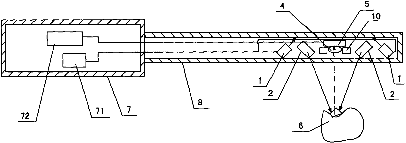
[0023] Embodiment two: if figure 2As shown, the structure of this embodiment is basically the same as that of Embodiment 1, the only difference is that a group of illuminating lamps 10 distributed in a ring shape for enhancing imaging illumination are arranged around the camera head, and 2- 5 LED light-emitting diodes; when the light source (LED light) is turned off, this group of lights makes the projected mesh geometric image become uniform illumination. At this time, the device can be used as a two-dimensional camera.


PUM


Abstract

The invention discloses a device for measuring the geometric shape of teeth. The device includes a handle and a probe. The probe is provided with a light source, a projection head and an imaging unit. The projection head is provided with a mesh geometric image; the light source emits incident light to illuminate On the projection head, the projection head alternately projects the same-shaped mesh geometric images onto the tooth surface at the angle of a symmetrical triangle to form different distorted mesh geometric images. Through the tooth surface, two different distorted mesh images Shaped geometric figure images are reflected into the imaging unit, and the perspective angle range between the projection light and the imaging light is ±10°~±30°. The characteristic is that the camera is set between the two projection heads and between the projection light and the imaging light. The perspective angle range is ±10°~±30°, and the distorted mesh geometric image is formed at a large perspective angle (greater than 30 degrees), which effectively avoids the shadow phenomenon of the mesh geometric image and improves the measurement sensitivity and precision.

Description

[0001] This application is a divisional application of the original application number 200810061900.1 for a patent application for invention, the filing date of which is May 23, 2008, and the title of the invention is "A device for measuring the geometric shape of teeth". technical field [0002] The present invention relates to an optical measuring device, in particular to a device for measuring tooth geometry. Background technique [0003] At present, there are many optical measurement devices for the teeth in the patient's oral cavity, such as the CEREC (Chair-side Economic Reconstruction of Esthetic Ceramic, digital clinical restoration system) device manufactured by Sirona Company, which was separated from Germany's Siemens. The graphic projection industrial measurement technology projects the parallel grid of light and dark linear stripes on the surface of the tooth, and images them on the two-dimensional CCD (Charge Coupled Device, Charge Coupled Device) camera at a pa...

Claims


Application Information

Patent Timeline
Patent Type & Authority Patents(China)
IPC IPC(8): A61B5/107A61C19/04
Inventor 罗南丁洪李同
Owner 宁波思达利光电科技有限公司
Learn More