
Synchronization power supply device, power supply synchronization method and silicon controlled rectifying system

A technology of synchronous power supply and synchronous pulse, which is applied in the direction of converting irreversible AC power input to DC power output, etc., can solve the problem of high manufacturing cost and power consumption of three-phase synchronous transformer, unsatisfactory adjustability and sensitivity, and pulse shift. The phase range cannot be adjusted, etc., to achieve the effect of simple and easy troubleshooting, fast and accurate pulse phasing process, and fast and accurate phasing process.

Inactive Publication Date: 2010-05-19
ZHUZHOU KORI CONVERTORS
View PDF0 Cites 1 Cited by
  • Summary
  • Abstract
  • Description
  • Claims
  • Application Information

AI Technical Summary

Problems solved by technology

[0003] The synchronous rectification technology that is widely promoted today is the first thyristor synchronous rectification technology. The thyristor needs a pulse to trigger it to be turned on during the synchronous rectification process. The pulse sent is determined by synchronous voltage positioning and offset voltage according to the anode voltage phase of the thyristor. The phase shift size realizes the synchronization of the pulse and the three-phase AC power supply. The synchronization voltage and the offset voltage can be collectively referred to as a synchronization signal. The synchronization power supply device is a device that sends the synchronization signal to make the trigger circuit send a trigger pulse. The existing synchronous power supply devices are divided into two types according to the control form: analog control type and digital control type. Since people have higher and higher requirements for rectification systems, especially for rectification accuracy and rectification stability, In the analog control system, a three-phase synchronous transformer is used as a synchronous power supply to set the phase of each pulse. When the phase sequence of a certain phase of the main power supply changes, all pulse phase sequences must be adjusted, so that a small fault requires Adjusting all three phases brings difficulty to the rectification, so the analog control type cannot meet the above requirements; the emergence of digital control type just meets the requirements of rectification accuracy and stability, and the typical one is the three-phase synchronous transformer
[0004] However, taking the three-phase synchronous transformer as an example, its circuit structure is relatively complicated, and the fault handling is cumbersome, and the pulse phasing process is very complicated. Once the phasing is achieved, the phase shift range of the pulse cannot be adjusted. In addition, the three-phase synchronous transformer has relatively high manufacturing cost and power consumption, which is uneconomical from the perspective of technical savings.

Method used


Image

  • Synchronization power supply device, power supply synchronization method and silicon controlled rectifying system
  • Synchronization power supply device, power supply synchronization method and silicon controlled rectifying system
  • Synchronization power supply device, power supply synchronization method and silicon controlled rectifying system

Examples


Embodiment Construction

[0044] For reference and clarity, technical terms, abbreviations or abbreviations used hereinafter are summarized as follows:

[0045] The following will clearly and completely describe the technical solutions in the embodiments of the present invention with reference to the accompanying drawings in the embodiments of the present invention. Obviously, the described embodiments are only some, not all, embodiments of the present invention. Based on the embodiments of the present invention, all other embodiments obtained by persons of ordinary skill in the art without creative efforts fall within the protection scope of the present invention.

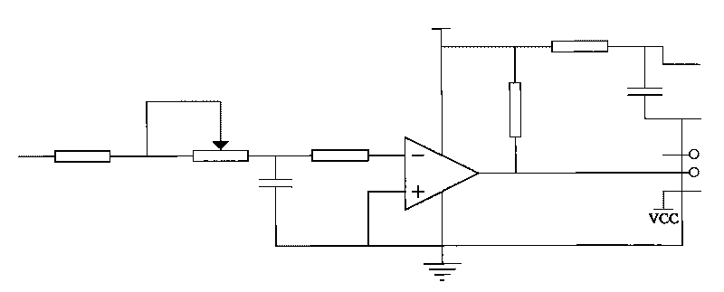
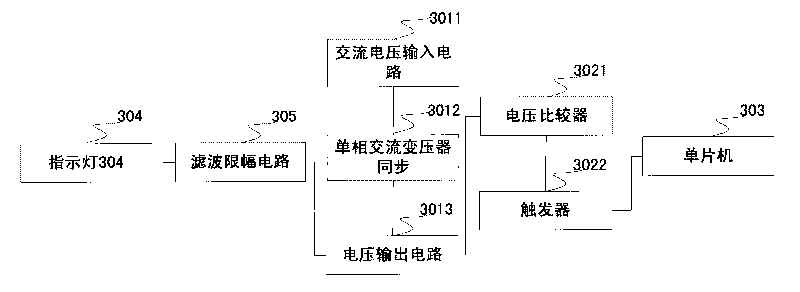
[0046] The invention provides a synchronous power supply device, a power supply synchronization method and a thyristor rectification system, which realize the synchronization of the power supply through a single-phase voltage.

[0047] figure 1It shows a structure of a synchronous power supply device disclosed in Embodiment 1 of the prese...


PUM


Abstract

The embodiment of the invention discloses a synchronization power supply device, comprising a synchronization power supply plate, a pulse trigger and a singlechip, wherein the synchronization power supply plate is used for converting the received single-phase high voltage into single-phase low voltage and outputting the single-phase low voltage to the pulse trigger; the output end of the pulse trigger is connected with an interrupt interface of the singlechip for outputting a synchronization pulse signal of a triggering singlechip, which is converted by the single-phase low voltage; the singlechip is used for processing the received synchronization pulse signal and outputting the signal, the synchronization power supply device takes the situation that the single-phase high voltage is converted into the single-phase low voltage as a trigger signal of the pulse trigger and outputs the trigger signal through the pulse trigger, and then the trigger signal is used as the synchronization pulse signal to be output to the singlechip, and the singlechip processes the synchronization pulse signal and then outputs the signals, so as to realize the purpose of single-phase voltage synchronization; a single-phase synchronization circuit is simple, compared with the prior art, the adjustability is greatly improved, and the fault treating procedure is simple and easy.

Description

technical field [0001] The invention relates to the technical field of synchronous rectification control, and more specifically relates to a synchronous power supply device, a power supply synchronization method and a thyristor rectification system. Background technique [0002] In recent years, with the development of electronic technology, the operating voltage of the circuit is getting lower and lower, while the current is getting higher and higher. Low-voltage operation is conducive to reducing the overall power consumption of the circuit, but it also puts forward higher requirements for power supply design. The emergence of synchronous rectification technology reduces the rectification loss at the output end of the switching power supply, improves the conversion efficiency, reduces the heat generation of the power supply itself, and initially solves the above problems, and has developed rapidly in recent years. [0003] The synchronous rectification technology that is ...

Claims


Application Information

Patent Timeline
Patent Type & Authority Applications(China)
IPC IPC(8): H02M7/12
Inventor 江贤春
Owner ZHUZHOU KORI CONVERTORS
Learn More