
Novel electric power electric transformer

A technology of power electronics and transformers, applied in electrical components, conversion equipment with reversible, AC power input is converted into DC power output, etc. The practical application and marketization process of electronic transformers can achieve the effect of reducing the floor space, reducing the overall cost and high voltage level.

Inactive Publication Date: 2010-05-12
CHINA ELECTRIC POWER RES INST +2
View PDF0 Cites 47 Cited by
  • Summary
  • Abstract
  • Description
  • Claims
  • Application Information

AI Technical Summary

Problems solved by technology

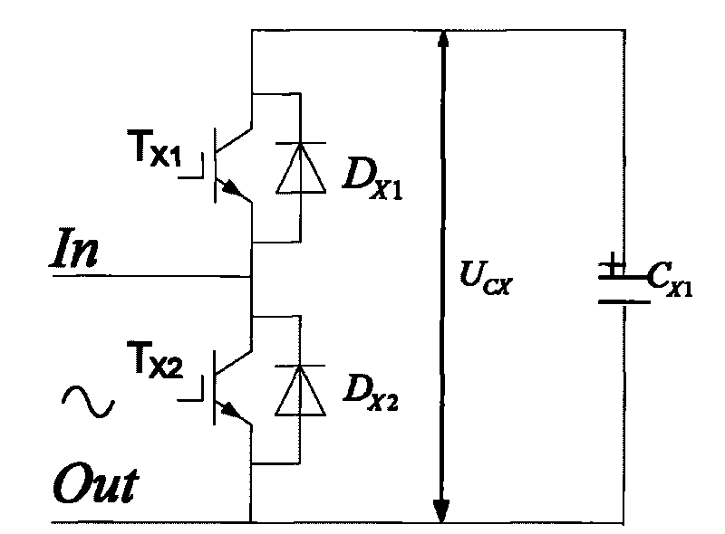
[0004] The purpose of the present invention is to provide a new type of power electronic transformer, which skillfully utilizes the existing half-bridge topology technology, and solves the problem of low operating efficiency of conventional power electronic transformers and the problem of switching devices on the input side. The problem of withstand voltage and voltage equalization is of great significance to accelerate the practical and marketization process of power electronic transformers

Method used


Image

  • Novel electric power electric transformer
  • Novel electric power electric transformer
  • Novel electric power electric transformer

Examples


Embodiment Construction

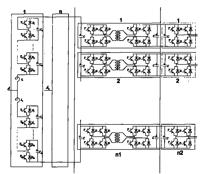
[0021] 1) Topological structure of the novel power electronic transformer of the present invention

[0022] The new power electronic transformer adopts a half-bridge topology. In order to facilitate the analysis of the structure of this type of power transformer, a structure diagram of a new power electronic transformer is given as follows: Figure 4 As shown, the figure shows a power electronic transformer with three inputs and three outputs, which is composed of three stages: high voltage stage, isolation stage and low voltage stage. The high voltage stage is composed of a switch tube T A1 , T A2 , T A3 , T A4 , T A5 , T A6 , T A7 , T A8 , T A9 , T A10 , T A11 , T A12 , T B1 , T B2 , T B3 , T B4 , T B5 , T B6 , T B7 , T B8 , T B9 , T B10 , T B11 , T B12 , T C1 , T C2 , T C3 , T C4 , T C5 , T C6 , T C7 , T C8 , T C9 , T C10 , T C11 , T C12 , power diode D A1 、D A2 、D A3 、D A4 、D A5 、D A6 、D A7 、D A8 、D A9 、D A10 、D A11 、D A12 、D ...


PUM


Abstract

The invention discloses a novel electric power electric transformer. The electric power electric transformer consists of a high-voltage level, an isolation level and a low-voltage level, wherein the high-voltage level comprises 2*N*n half-bridge topology first power modules; the isolation level consists of N1 second level power modules, and each second power module comprises a medium high frequency wave chopper part, a medium high frequency transformer part and a medium high frequency synchronous rectifier part; and the low-voltage level consists of N2 level third power modules. The electric power electric transformer skillfully utilizes the prior half-bridge topology structure technique, better solves the problems of low operating efficiency, voltage resistance and voltage sharing of switch devices on the input side and big volume of an input filter existing in the common electric power electric transformer, and simultaneously realizes reactive power control of the high-voltage level and the low-voltage level, quality control of electric energy and limitation of failure current, improves the practicability of the device and quickens commercialization of the electric power electric transformer.

Description

technical field [0001] The invention relates to the field of power electronic devices, in particular to a novel power electronic transformer. Background technique [0002] In the smart grid, power electronic transformers can provide flexible access solutions for microgrids, distributed energy or renewable energy, can solve power quality problems in power systems, and can fully meet power users' requirements for power supply reliability, security, and flexibility. , economy and power supply quality requirements, has broad application prospects. The power electronic transformer detects the relevant electrical parameters of each node of the power system on the input side, and adjusts the relevant control quantities on the input side of the power electronic transformer in real time, so as to continuously, smoothly and quickly adjust the power flow of the power system to achieve effective control of the operating state of the power system. Purpose: The power electronic transform...

Claims


Application Information

Patent Timeline
Patent Type & Authority Applications(China)
IPC IPC(8): H02M7/72
CPCH02M2007/4835H02M7/4835
Inventor 周飞王志冰张皎赵波
Owner CHINA ELECTRIC POWER RES INST
Learn More