
Power supply circuit for active electronic transformer

A technology for electronic transformers and power supply circuits, which is applied in the direction of inductors, circuits, voltage/current isolation, etc., and can solve the problem of limiting the operating current threshold of active electronic current transformers, limiting the wake-up current and the maximum current, etc. problem, to achieve the effect of automatic adjustment and increase the current input range

Inactive Publication Date: 2010-05-12
PINGGAO GRP
View PDF0 Cites 2 Cited by
  • Summary
  • Abstract
  • Description
  • Claims
  • Application Information

AI Technical Summary

Problems solved by technology

Since the power supply voltage of the power supply circuit cannot be too large or too small, the wake-up current and the maximum current are limited, that is, the operating current threshold of the active electronic current transformer is limited.

Method used


Image

  • Power supply circuit for active electronic transformer
  • Power supply circuit for active electronic transformer
  • Power supply circuit for active electronic transformer

Examples


Embodiment Construction

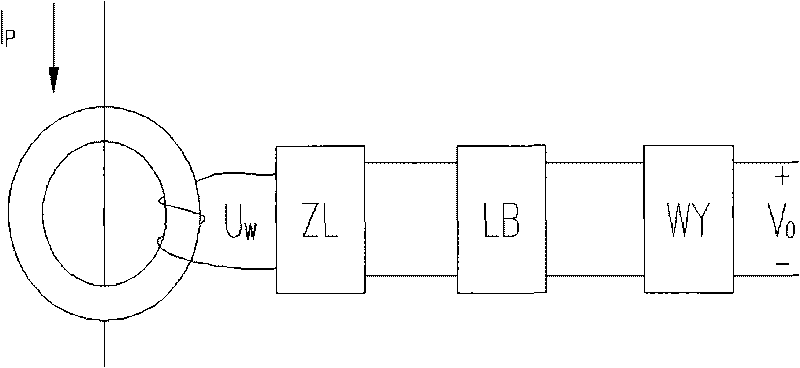
[0012] Such as figure 1 As shown, the existing active electronic transformer power supply circuit includes a current transformer, and the output terminal voltage U of the current transformer is W The rectifier circuit ZL, filter circuit LB and voltage stabilizing circuit WY are connected in sequence, and the working voltage V of the active electronic current transformer is output. O ; where I P is the current in the high-voltage line, and the arrow represents the direction of the current.

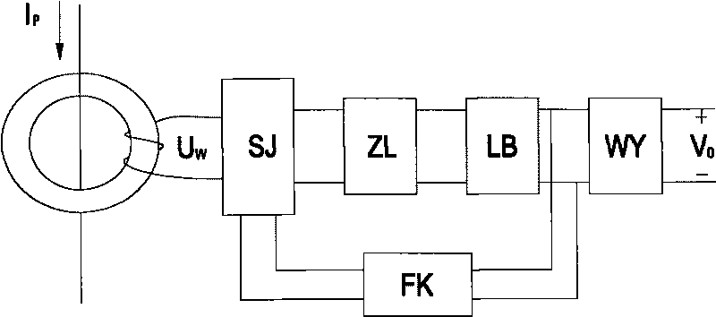
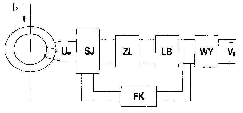
[0013] Such as figure 2 As shown, the active electronic transformer power supply circuit of this embodiment is provided with a nonlinear attenuation circuit SJ between the output terminal of the current transformer and the rectification circuit ZL, the attenuation of the attenuation circuit SJ is adjustable, and the filter circuit LB The output is connected to the control terminal of the above-mentioned nonlinear attenuation circuit SJ through the nonlinear feedback module FK.

[0014]...


PUM


Abstract

The invention relates to a power supply circuit for an active electronic transformer, which comprises a current transformer of which the output end is orderly connected with a rectifying circuit, a filter circuit and a voltage stabilizing circuit; and an attenuator circuit is arranged between the output end of the current transformer and the rectifying circuit; therefore, the current input upper limit of normal power supply of the power supply circuit is improved, and the power supply circuit can work normally under high working voltage.

Description

technical field [0001] The invention relates to a power supply circuit in a line power supply mode of a high-voltage side circuit board of an active electronic current transformer. Background technique [0002] The signal processing part of the high-voltage side of the active electronic current transformer has no self-power supply capability, and an additional power supply is required. At present, there is a method of taking power from the line through a small current transformer to provide power for the high-voltage side signal processing. However, the charging voltage obtained by this power-taking method is easily affected by the magnitude of the line current, so the power supply circuit in this method has two important parameters, the wake-up current and the maximum current. The wake-up current is the initial minimum current of the power supply, and the maximum current refers to the maximum current of the power supply circuit. Since the power supply voltage of the power...

Claims


Application Information

Patent Timeline
Patent Type & Authority Applications(China)
IPC IPC(8): H01F38/28H01F38/32G01R15/18
Inventor 王红庆平海涛刘易雄
Owner PINGGAO GRP
Learn More