
Multi-loop decorative lamp and decorative lamp bank

A decorative lamp and multi-circuit technology, applied in decorative arts, special patterns, lighting devices, etc., can solve the problems of small decorative lamps, waste of main lines, complicated circuit design, etc., and achieve simplified circuit structure, cost reduction, beautiful and coordinated appearance Effect

Inactive Publication Date: 2010-05-05
HE SHAN LIDE ELECTRONICS ENTERPRISE CO LTD
View PDF0 Cites 3 Cited by
  • Summary
  • Abstract
  • Description
  • Claims
  • Application Information

AI Technical Summary

Problems solved by technology

There are many disadvantages in this design. First, there are too many main lines close to the control chip. If there are N loops, there will be N+1 main lines, while the main lines away from the control chip will gradually decrease. The lines of the entire decorative light are tapered. This decorative light The appearance is ugly, the overall decorative effect is poor, and the main line is also particularly wasted; secondly, if N loops are to be realized, N main lines must be connected to the control chip for control. If the decorative lamp uses more loops, the entire The circuit design is particularly complicated; similarly, if there are more loops, the pins of the control chip used will also increase, the corresponding control circuit board will increase accordingly and the electronic components will also increase accordingly, and the shape of the decorative lamp will appear large. Small defects, the more circuits of decorative lights, the higher the cost, this design is not easy to be widely used in the market

Method used


Image

  • Multi-loop decorative lamp and decorative lamp bank
  • Multi-loop decorative lamp and decorative lamp bank
  • Multi-loop decorative lamp and decorative lamp bank

Examples


Embodiment 1

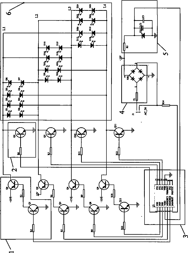
[0036] Please refer to image 3 As shown, in this embodiment, the multi-loop control circuit of the present invention includes a rectification unit 4 connected to the alternating current AC_IN, four main lines L1, L2, L3, L4 respectively connected to the output terminals of the rectification unit 4 and voltage regulators Filtering unit 5. Two groups of LEDs connected in parallel at one end of any two main lines on the four main lines L1, L2, L3, L4, wherein the polarity of the two groups of LEDs is opposite, a total of 16 LED diodes D1 to D16, on the four main lines L1 The other end of , L2, L3, L4 is also connected with the first control switch 1 and the second control switch 2, the input ends of the first control switch 1 and the second control switch 2 are respectively connected with the output end of the control unit 3, the 12V The power supply terminal is connected to the main line through the first control switch 1, and the main line is grounded through the second contro...

Embodiment 2

[0049] Please refer to the attached Figure 4 , 5 , 6, the present invention also provides a decorative lamp using the multi-loop control circuit described in Embodiment 1, the decorative lamp includes at least two main wires, a controller 15, a power wire 60 connected externally to the controller 15, and a The lamp tube 22 that controller 15 is connected, comprises control circuit board 70 (this control circuit board is an optional component) and the control chip 75 that is arranged on this control circuit board 70 in the controller 15, and this control chip 75 can choose model It is the CPU of 78P153, and the control chip 75 is the control unit 3 in the first embodiment. The control circuit board 70 also includes multiple groups of control switches electrically connected to the control unit 3, and each group of control switches includes the first control switch and a second control switch, the first end of each main line is connected to the power supply end through the firs...

Embodiment 3

[0059] Please refer to Figure 7 , 8 , 9, and 10 show that the present invention is another decorative lamp using the multi-loop control circuit described in Embodiment 1. The difference between this embodiment and Embodiment 2 is that it does not need to be installed outside the lamp tube in Embodiment 2. Instead, the control circuit board in the controller is directly installed in the lamp tube; the decorative lamp in this embodiment includes a control circuit board 70 and four main wires 40, 41, 42 connected to the control circuit board 70 , 43 and two groups of LEDs connected in parallel on any two main lines, the polarity of the two groups of LEDs is opposite, the control circuit board 70 includes a control unit 3, a plurality of groups of control switches connected with the control unit 3, each group of control switches includes The first control switch and the second control switch, the four main lines 40, 41, 42, 43 are respectively connected to each group of control ...


PUM


Abstract

The invention discloses a multi-loop decorative lamp, comprising a controller, a lighting tube and at least two main lines; the controller comprises a control unit, at least two first control switches and at least two second control switches; the first end of each main line is connected with a power supply end through the first control switch, and is grounded through the second control switch; the control ends of the first control switch and the second control switch are connected with the output end of the control unit; the first control switch and the second control switch are switched on or off according to the control signal output by the control unit; the lighting tube comprises a core wire; the main lines are arranged in the core wire; two groups of LEDs with opposite polarities are connected between the second ends of any two main lines in parallel; a longitudinal through hole is arranged along the length direction of the core wire; an open slot is arranged along the longitudinal through hole; the LEDs are arranged in the longitudinal through hole; and a transparent layer is coated outside the core wire. The invention adopts N main lines to achieve N*(N-1) loops, thereby reducing the number of the main lines, simplifying the circuit structure, and also reducing the product cost.

Description

【Technical field】 [0001] The invention relates to a decorative lamp, in particular to a multi-circuit decorative lamp and a decorative lamp group. 【Background technique】 [0002] In order to achieve a good decorative effect, the traditional decorative light strings are generally set to have the function of strobe or color change or both, especially the Christmas decorative light strings. In order to create a icy and snowy atmosphere, a snow Effect of the decorative light string more and more people of all ages. The circuit principle diagram of decorative lamp product in this prior art refers to figure 1 As shown, the existing design is a circuit design using N+1 main lines to realize N loops. The product shown in the figure includes 16 series-connected light strings 10, which are composed of three LED diodes connected in series. One end of each series light string 10 is connected in parallel with the main line L17, and the main line L17 is electrically connected with a DC ...

Claims


Application Information

Patent Timeline
Patent Type & Authority Applications(China)
IPC IPC(8): F21V23/00F21V15/02H05B37/02F21Y101/02
CPCF21S4/003F21W2121/00F21W2121/006F21Y2101/02H05B33/0824F21S4/001F21S4/10F21S4/20F21Y2115/10H05B45/44
Inventor 樊邦扬
Owner HE SHAN LIDE ELECTRONICS ENTERPRISE CO LTD
Learn More