Method for constructing liquified discarded soil in construction of subaqueous structure

A construction method and structure technology, applied in construction, hydraulic engineering, infrastructure engineering, etc., can solve the problems of expansion, destruction of surrounding buildings, high construction costs, etc., and achieve the effects of reducing costs, avoiding landslides, and shortening the construction period

Inactive Publication Date: 2010-04-07
卢如年
View PDF0 Cites 11 Cited by
  • Summary
  • Abstract
  • Description
  • Claims
  • Application Information

AI Technical Summary

Problems solved by technology

Due to the excavation of the foundation pit, the balance of the soil is destroyed, and soil landslides are prone to occur, resulting in the destruction of surrounding buildings; when the foundation pit is excavated under the geological conditions of underwater soft soil or sandy soil, in order to stabilize the slope, excavation The amount of work is extremely large, resulting in high construction costs and long construction periods; after the excavation of the foundation pit, there will be silting at the bottom and incomplete dredging, resulting in a weak interlayer at the bottom, leaving hidden dangers of landslide accidents
[0005] 3. For underwater reclamation of cofferdams, the traditional construction method uses riprap to squeeze silt in addition to excavating foundation pits. The obvious disadvantage of this method of riprap silt is that the bottom layer will As the soil is squeezed away, it will continue to expand, resulting in a large amount of stone and high cost; there will also be a weak interlayer at the bottom of the riprap embankment, and the completed cofferdam will have a landslide accident hazard

Method used


Image

  • Method for constructing liquified discarded soil in construction of subaqueous structure
  • Method for constructing liquified discarded soil in construction of subaqueous structure
  • Method for constructing liquified discarded soil in construction of subaqueous structure

Examples


Embodiment 1

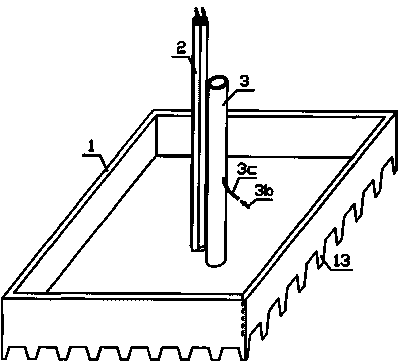
[0065] see Figures 1 to 5 , this embodiment is: the high-pressure water or gas conveying branch pipe 4 is installed under the bottom of the box, and the injection holes are directly opened on the branch pipe 4; the method of liquefying the soil is to inject high-pressure water or gas.

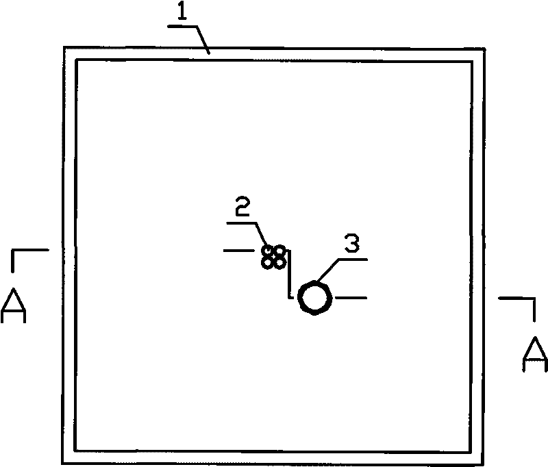
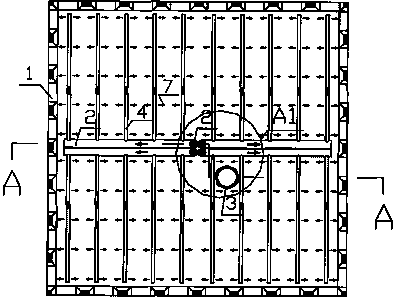
[0066] 1. If Figures 1 to 2 , in the prefabrication field, make a box body 1 with a bottom plate and an upper opening, and there are blade feet 13 around the bottom of the box (the shape of the blade feet can be other shapes); install 4 high-pressure water or gas main pipes 2 in the box. There can be multiple high-pressure water or gas delivery pipes, depending on the specific situation, and the same for other embodiments. The 4 main pipes 2 penetrate the bottom of the tank and are respectively connected with 4 groups of high-pressure water or gas conveying branch pipes 4 under the bottom of the tank; a mud discharge pipe 3 that penetrates the bottom of the tank is also installed in the tank...

Embodiment 2

[0070] see Figures 6 to 11 , this embodiment is: the high-pressure water or gas conveying branch pipe 4 is installed in the bottom plate of the box, and the high-pressure water or gas is injected through the nozzle 6; the method of liquefying the soil is to inject high-pressure water or gas.

[0071] 1. If Figures 6 to 8 , in the prefabrication field, make a box body 1 with an upper opening with a bottom plate, and there are blade feet 13 around the bottom of the box (the shape of the blade feet can be other shapes); install 4 high-pressure water or gas main pipes 2 in the box, the 4 The main pipe 2 is respectively connected with 4 groups of high-pressure water or air conveying branch pipes 4 in the box, and there are multiple outlets on each branch pipe 4 which are respectively connected with independent water or air gun rods 5; the cross-sectional area of ​​each conveying main pipe 2 is larger than 1.2 times the sum of the cross-sectional areas of the branch pipes 4 conne...

Embodiment 3

[0075] see Figures 12 to 16 , This embodiment is similar to Embodiment 2, the difference is that the nozzle 6 is changed to a pressure vibrator 8; the method for liquefying the soil is that the pressure vibrator 8 generates high-frequency vibration.

[0076] 1. If Figures 12 to 16 , the production of the box 1 and the production of the high-pressure liquid or gas conveying main pipe 2, the conveying branch pipe 4 and the mud discharge pipe 3 are the same as those of the embodiment 2, and the size of the cross-sectional area of ​​each pipe is also the same as that of the embodiment 2.

[0077] Several pressure vibrators 8 are installed at the end of each gun rod 5, and its power source is provided by a pressure machine (such as pulse hydraulic pump, pulse air pump) that can generate periodic positive and negative pressure, and the transmission method is through 4 high-pressure The liquid or gas conveying main pipe 2 reaches the pressure vibrator 8 through the conveying branc...


PUM


Abstract

The invention relates to a method for constructing liquified discarded soil in the construction of a subaqueous structure, which comprises the following steps: (1) manufacturing a structure with a bottom plate or a fence; (2) installing a vibrator or a high-pressure water or high-pressure gas spraying device at the lower part of the bottom plate or the fence of the structure; (3) generating vibration by the vibrator installed at the lower part of the bottom plate or the fence, or spraying out a high-pressure water column or gas by the high-pressure water or high-pressure gas spraying device and liquifying a soil layer within a sinkage range of the structure; and (4) installing a slurry discharge pipe on the bottom plate of the structure in a way of penetrating through the bottom plate, installing high-pressure gas spraying devices at the lower part and the middle part of the slurry discharge pipe, discharging slurry under the function of high-pressure gas sprayed by the high-pressure gas spraying devices and enabling the structure to continuously sink. The construction of constructing a large bridge foundation, a subaqueous tank body, a subaqueous bunker, a caisson of a gravity type wharf or a revetment, a sand filling or rubble tipping embankment of sea filling cofferdam engineering, a caisson or a rubble tipping embankment of a bulwark or a jetty and the like is safe, the cost is lowered, and the construction period is shortened.

Description

technical field [0001] The invention relates to a liquefied spoil construction method for constructing underwater structures. Under the condition of soft soil or sandy soil underwater, the construction of bridge foundation, underwater tank, underwater bunker, gravity wharf or caisson for revetment, sand filling of sea reclamation cofferdam project or construction of riprap berm, This technology is applicable to the construction of caisson or riprap embankments of breakwaters or diversion dikes. Background technique [0002] Construction of bridge foundations, underwater tanks, underwater bunkers, caissons for gravity wharves or revetments, sand filling or riprap for reclamation cofferdams all over the world in soft soil or sandy soil conditions of rivers, rivers and seas The construction of caisson or riprap embankments of berms, breakwaters or diversion dikes is becoming more and more common, and the scale is getting larger and larger. It can be seen that it is very urgent...

Claims


Application Information

Patent Timeline
IPC IPC(8): E02D15/08E02D23/08E02B3/04
CPCE02D15/08E02B3/06E02D23/08Y02A10/11
Inventor 卢如年
Owner 卢如年
Why Eureka
Try Eureka