
Method and device for dynamically determining a segment for an angular spread, inside which fuel is injected into an internal combustion engine

A technology of fuel injection, angle range, applied in the direction of fuel injection control, internal combustion piston engine, combustion engine, etc.

Inactive Publication Date: 2010-03-31
CONTINENTAL AUTOMOTIVE GMBH
View PDF5 Cites 2 Cited by
  • Summary
  • Abstract
  • Description
  • Claims
  • Application Information

AI Technical Summary

Problems solved by technology

This problem cannot currently be solved in the known prior art

Method used


Image

  • Method and device for dynamically determining a segment for an angular spread, inside which fuel is injected into an internal combustion engine
  • Method and device for dynamically determining a segment for an angular spread, inside which fuel is injected into an internal combustion engine
  • Method and device for dynamically determining a segment for an angular spread, inside which fuel is injected into an internal combustion engine

Examples


Embodiment Construction

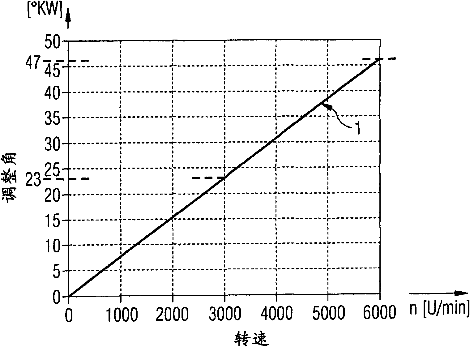
[0031] The invention mainly relates to the dynamic determination of the available injection range IRu of a segment S which is optimized in particular such that subsequent reinjections can be carried out for regeneration of the particle filter of a diesel engine, for example, without affecting the engine properties. A further essential aspect of the invention is that the available injection range IRu of the subsection S can be shifted in the retarding direction or vice versa in the advancing direction as required in its relative position as a function of the crankshaft angle. Next, the available injection range IRu is determined on the basis of the angular range and its relative position by means of the waiting time and the rotational speed gradient. The controller can thus calculate the maximum possible injection range IRu for each rotational speed n using a program designed for the stored algorithm or retrieve it from a table. It is thus possible to optimally use the availabl...


PUM


Abstract

The invention relates to a method and a device for dynamically determining a segment for an angular spread, in which fuel is injected into an internal combustion engine. According to the invention, the useful injection range (IRu) and / or the relative position of the segment comprising the angular spread, in which a fuel injection can be carried out especially during a multiple injection, are variable. A corresponding adaptation of the useful injection range (IRu) can advantageously trigger a subsequent injection impulse, as required, for example, for a regeneration module of a diesel particlefilter. The adaptation is carried out according to an operating parameter, for example according to the rotational speed gradient.

Description

technical field [0001] The invention relates to a method and a device of the type specified in the accompanying claims 1 and 11 for dynamically determining segments for the angular range within which fuel can be injected into an internal combustion engine. Background technique [0002] It is generally known to control and monitor an internal combustion engine by means of an engine controller (controller). For this purpose, internal combustion engines are equipped with injection systems, such as common rail or pump-nozzle injection systems. In order to inject fuel into the various cylinders of the internal combustion engine, fuel injectors (injectors) are provided on the cylinders for each cylinder. In order to be able to carry out multiple injections, especially with pre-injection and post-injection, piezoelectric injectors are generally used, since this type not only allows very fast switching times and thus the smallest injection quantities can be controlled, but also has...

Claims


Application Information

Patent Timeline
Patent Type & Authority Applications(China)
IPC IPC(8): F02D41/26F02D41/34F02D41/40
CPCF02D41/263F02D41/401F02D41/405Y02T10/44F02D41/402F02D41/029Y02T10/40
Inventor S·阿谢尔H·-J·韦霍夫
Owner CONTINENTAL AUTOMOTIVE GMBH
Learn More