
Yarn feeder with an overload-protected anchoring clip

A technology for conveying equipment and grippers, which is applied to friction-clamped detachable fasteners, mechanical equipment, threaded fasteners, etc., and can solve problems such as damage, loosening, and deformation of the gripper

Active Publication Date: 2010-03-31
MEMMINGER IRO GMBH
View PDF1 Cites 2 Cited by
  • Summary
  • Abstract
  • Description
  • Claims
  • Application Information

AI Technical Summary

Problems solved by technology

[0004] If the fastening screw is tightened too much, the holder can be broken or damaged, i.e. the holder can become deformed, e.g. fall apart
This oversight renders the entire yarn delivery device inoperable as it can no longer be securely mounted to the knitting machine

Method used


Image

  • Yarn feeder with an overload-protected anchoring clip
  • Yarn feeder with an overload-protected anchoring clip
  • Yarn feeder with an overload-protected anchoring clip

Examples


Embodiment Construction

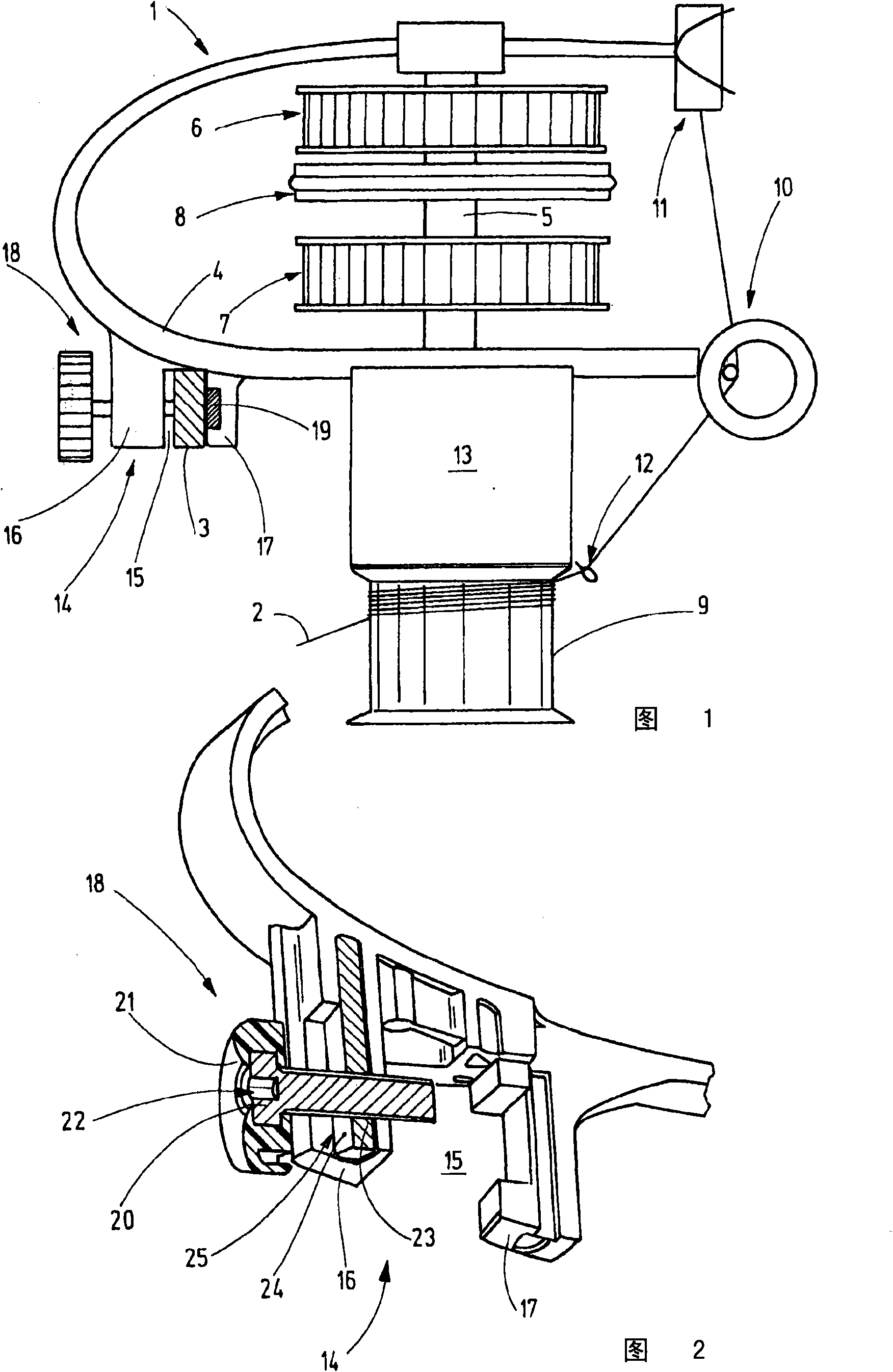
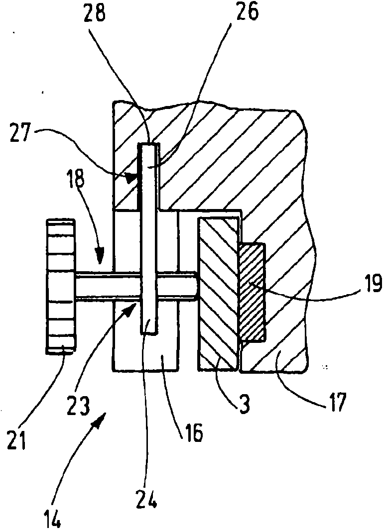
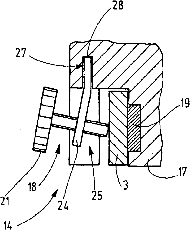
[0022] figure 1 Shown is a yarn delivery device 1 configured as a normal yarn delivery device and arranged to deliver a yarn 2 to a yarn consumption location, for example to a knitting location of a knitting machine. Typically, a plurality of such yarn delivery devices 1 are arranged on a carrier 3 of a circular knitting machine, said carrier being configured in this case as a closed ring spindle. figure 1 A vertical section of the carrier 3 is shown. The yarn delivery device 1 comprises a central holder 4 on which, for example, a vertically arranged, rotatably supported shaft 5 with pulleys 6, 7 for making one of the pulleys 6, 7 A clutch 8 in selective torque transmitting engagement with the shaft 5 and a yarn delivery wheel 9 connected to the shaft 5 at its lower end in a torque resistant manner. Additional elements can also be arranged on the holder 4, i.e. for example a yarn brake 10, a yarn guiding device 11, 12, a functional housing 13, or other not shown for example ...


PUM


Abstract

A yarn feeder according to the invention or other device has a clip (14) with overload protection in the form of a force-limiting means (25). The latter is preferably formed by a deformable wearing part, for example in the form of a sheet-metal piece (24), which bears the attachment screw (18). The sheet-metal piece (24) is dimensioned with respect to its flexural strength in such a manner that itfirstly permits reliable tightening of the clip (14), but secondly prevents damage to the clip (14), in particular the expansion thereof.

Description

technical field [0001] The present invention relates to a device, in particular to a yarn delivery device, comprising a clamp for fastening the device to a carrier, such as a knitting machine, and comprising a clamping screw. Background technique [0002] Document DE 10219537B4 discloses, for example, a yarn delivery device that is widely used on knitting machines in order to deliver the yarn to the knitting position. The yarn delivery device includes a central holder with a fastening gripper on one end. The holder is arranged to support the yarn delivery device on a carrier, for example in the configuration of a metal ring spindle, which is arranged on a circular knitting machine and a plurality of yarn delivery Equipment extends radially from the carrier. [0003] On the clamp of the center holder there are provided clamping screws which can be tightened in order to fasten the clamp to the carrier. The clamping screw is screwed into a corresponding threaded hole. If t...

Claims


Application Information

Patent Timeline
IPC IPC(8): D04B15/48
CPCD04B15/48F16B31/02F16B2/065
Inventor R·考夫曼P·罗思富斯
Owner MEMMINGER IRO GMBH
Learn More