Measuring method of tunnel shield posture

A measurement method and technology for tunnel shielding, which are applied in tunnels, earth-moving drilling, mining equipment, etc., can solve the problems that affect the progress of the project, the automatic measurement system is prone to problems, and is difficult to repair, so as to save project costs and ensure measurement accuracy. and stability, the effect of simplifying the measurement process

Inactive Publication Date: 2010-03-31
SHANGHAI MECHANIZED CONSTR GRP
View PDF7 Cites 20 Cited by
  • Summary
  • Abstract
  • Description
  • Claims
  • Application Information

AI Technical Summary

Problems solved by technology

[0002] Shield attitude measurement includes manual attitude measurement and automatic attitude measurement. Manual attitude measurement is to calculate the head and tail deviation of the shield machine by measuring the fixed scale installed on the shield machine with manual instruments. Automatic attitude measurement is a combination of measurement and instrumentation. Instrument and computer software and hardware technology are integrated, and the system has the function of dynamic measurement of shield posture. At present, the domestic automatic measurement system is mainly the ROBOTEC automatic measurement system developed by Japan's Calculus Workshop and the VMT automatic measurement system developed by Germany. However, due to the automatic measurement system It is prone to problems, and it is not easy to repair and will affect the progress of the project, so most of the domestic shield machines are equipped with manual measurement systems

Method used


Image

  • Measuring method of tunnel shield posture
  • Measuring method of tunnel shield posture
  • Measuring method of tunnel shield posture

Examples


Embodiment Construction

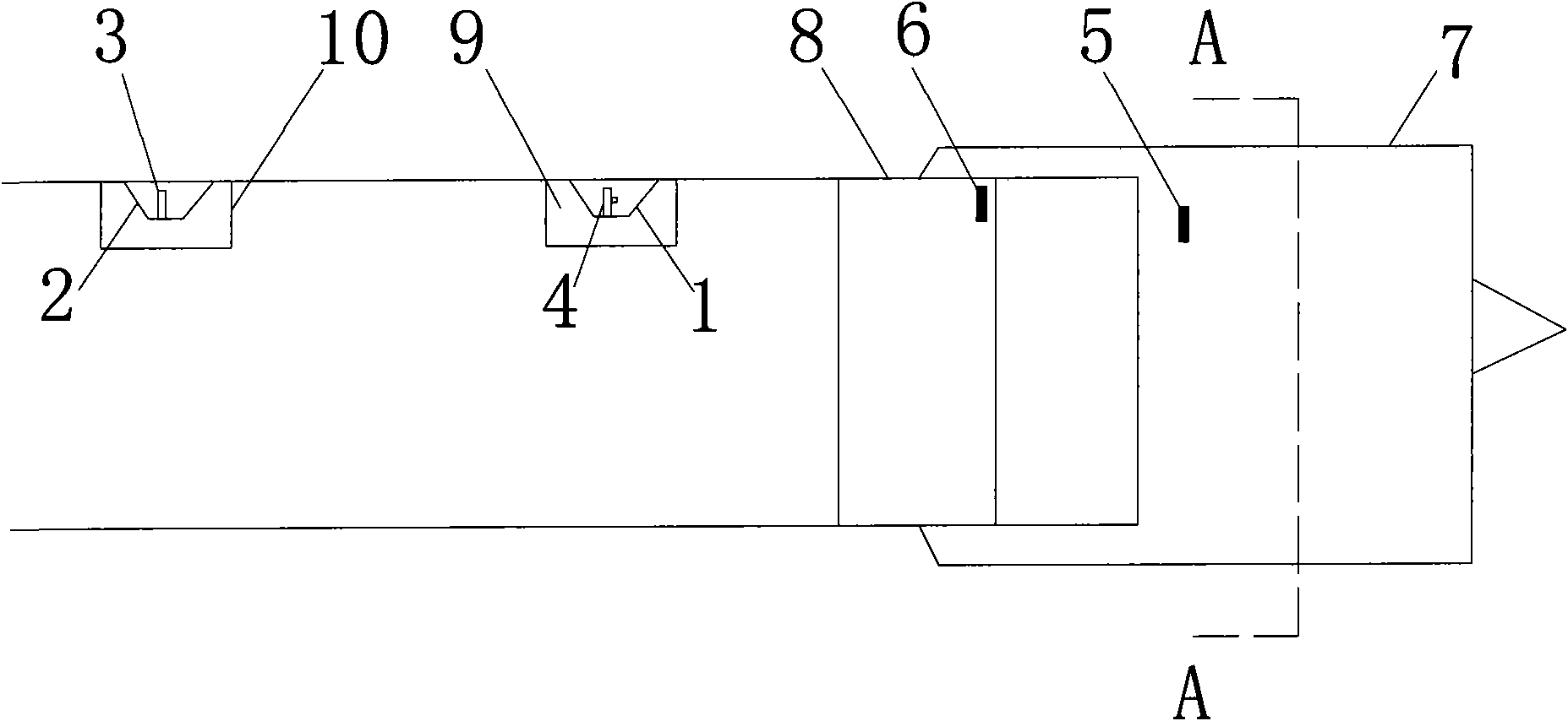
[0056] Attached below Figure 1-9 A preferred embodiment of the method of the present invention will be described in detail.

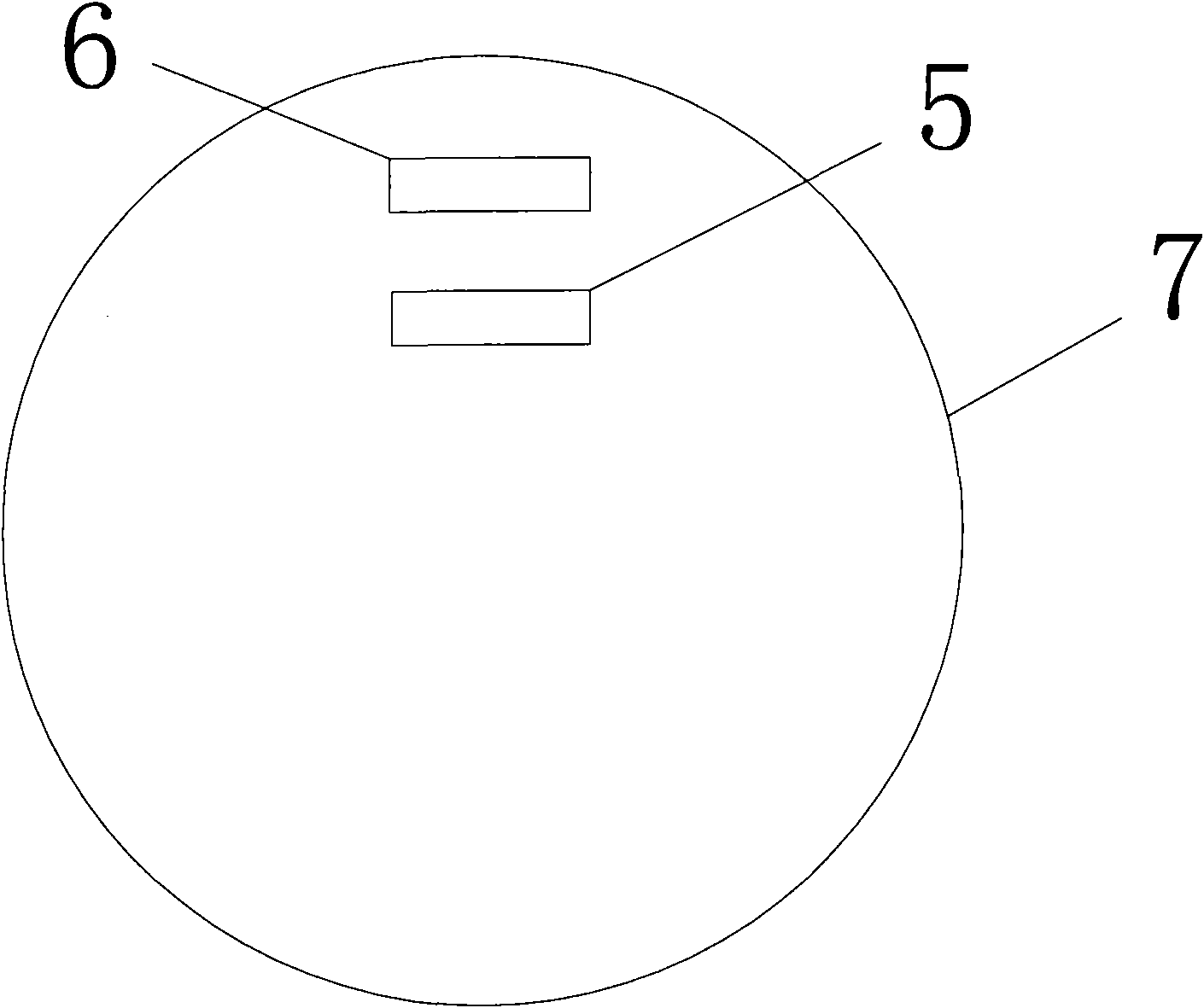
[0057] like figure 1 , 9As shown, a front instrument platform 1 and a rear instrument platform 2 are arranged on the segment 8 assembled at the rear of the shield machine 7 one in front of the other at a distance of 30 to 35 cm from the top of the segment 8, and the interval at the lower part of the front instrument platform 1 is 40 cm. The front instrument console 9 is arranged on the left and right, the theodolite 4 is arranged at intervals on the front instrument platform 1; the rear instrument console 10 is arranged at an interval of about 40 cm at the bottom of the rear instrument platform 2, and the prism 3 is arranged on the rear instrument platform 2, the structural representation of the prism 3 like Figure 5 shown. Surveyors stand on the instrument consoles 9 and 10 and operate the theodolite 4 or prism 3 for measurement. like image 3 ...


PUM


Abstract

The invention provides a measuring method of tunnel shield posture, comprising the following steps: 1. respectively arranging a theodolite, a prism, a front ruler and a rear ruler; 2. calculating the design coordinates of the front ruler and the rear ruler according to the design coordinates of the head part and the tail part of a shield machine and the relative position among the front ruler, the rear ruler and the shield machine, and calculating the design included angles alphafront of the prism, the theodolite and the front ruler and the included angles alpharear of the prism, the theodolite and the rear ruler; 3. using the theodolite to respectively measure the included angles betafront of the prism, the theodolite and the front ruler and the included angles betarear of the prism, thetheodolite and the rear ruler; 4. according to the design coordinates of the front ruler and the rear ruler and the coordinates of the theodolite, calculating the distance Sfront between the front ruler and the theodolite and the distance Srear between the rear ruler and the theodolite; 5. calculating the plane deviation of the front ruler and the rear ruler; 6. and according to the plane deviation of the front ruler and the rear ruler, calculating the plane deviation of the head part and the tail part of the shield machine in horizontal direction. The invention improves measurement precision, simplifies measurement process and greatly saves engineering cost.

Description

technical field [0001] The invention relates to an engineering measurement technology, which is especially suitable for the engineering measurement method of the forward attitude of the shield in the tunnel, and is a method for measuring the attitude of the tunnel shield. Background technique [0002] Shield attitude measurement includes manual attitude measurement and automatic attitude measurement. Manual attitude measurement is to calculate the head and tail deviation of the shield machine by measuring the fixed scale installed on the shield machine with manual instruments. Automatic attitude measurement is a combination of measurement and instrumentation. Instrument and computer software and hardware technology are integrated, and the system has the function of dynamic measurement of shield posture. At present, the domestic automatic measurement system is mainly the ROBOTEC automatic measurement system developed by Japan's Calculus Workshop and the VMT automatic measureme...

Claims


Application Information

Patent Timeline
Patent Type & Authority Applications(China)
IPC IPC(8): E21D9/093G01C1/02
Inventor 王斌俞靓姜旭贤戴建雄张朝彪孔利明
Owner SHANGHAI MECHANIZED CONSTR GRP
Why Eureka
Try Eureka