
Apparatus for conveying packages

A technology for packaging and conveying devices, which is applied in the directions of conveyor objects, transportation and packaging, and can solve the problems of limited transmission speed and packaging speed of equipment.

Active Publication Date: 2010-03-24
KRONES AG
View PDF1 Cites 8 Cited by
  • Summary
  • Abstract
  • Description
  • Claims
  • Application Information

AI Technical Summary

Problems solved by technology

However, such devices are limited by their transfer speed and packing speed

Method used


Image

  • Apparatus for conveying packages
  • Apparatus for conveying packages
  • Apparatus for conveying packages

Examples


Embodiment Construction

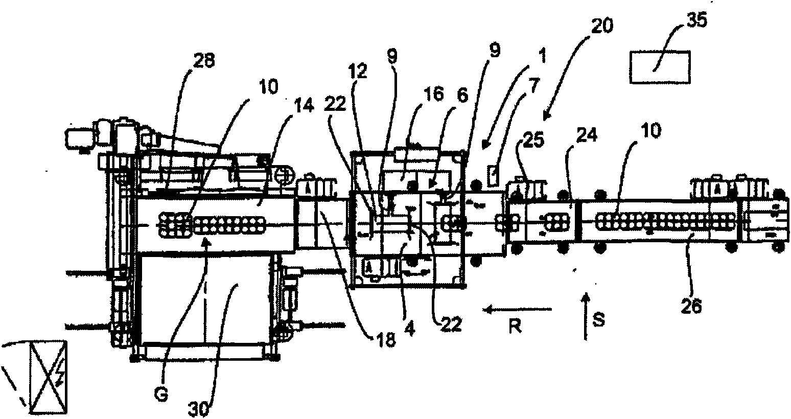
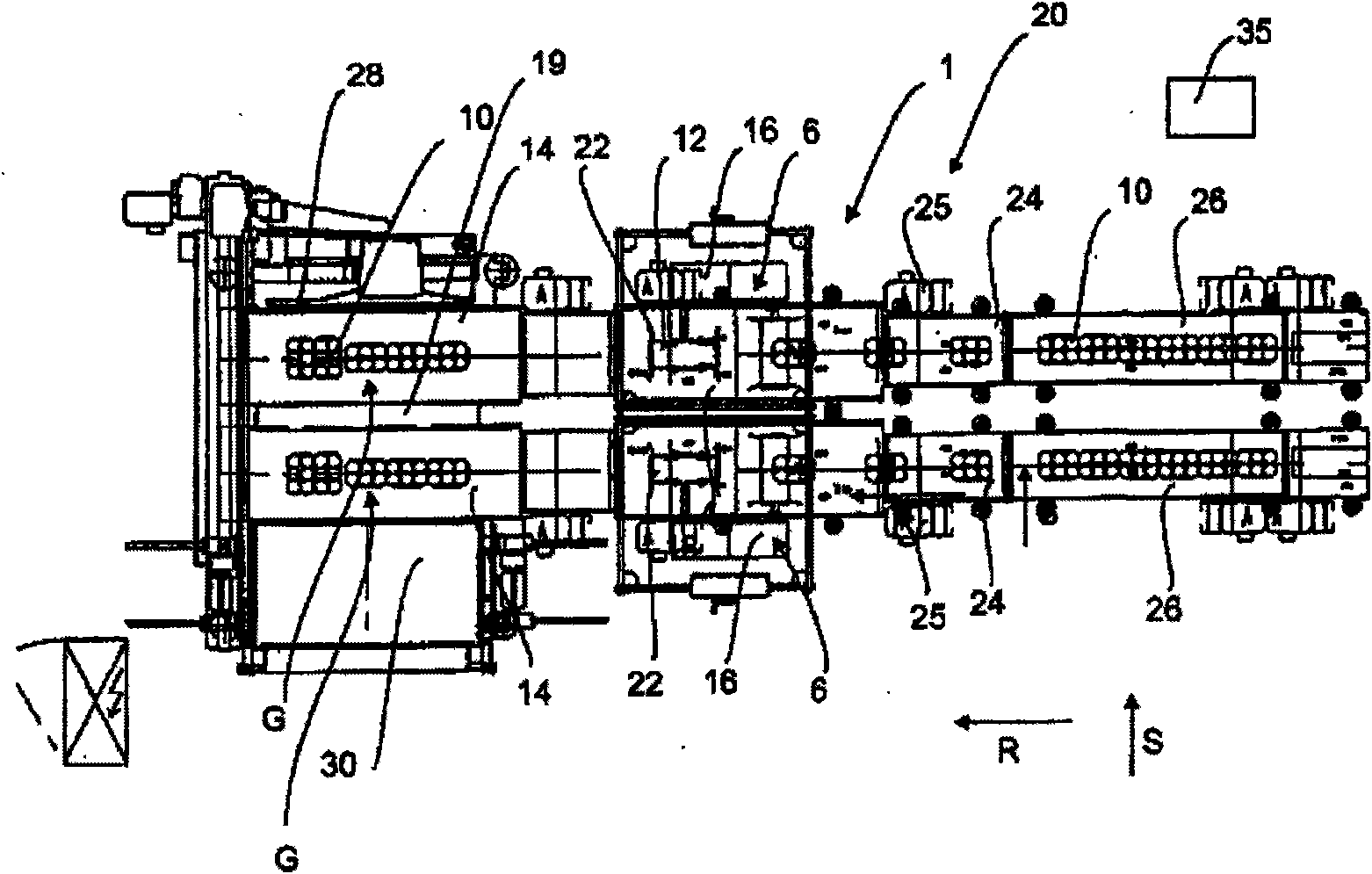
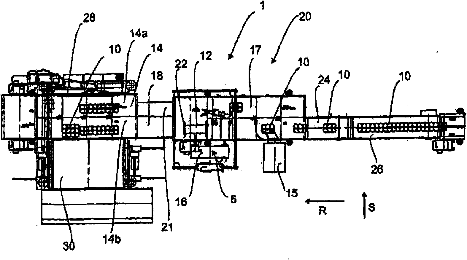
[0026] figure 1 Shown is an installation 20 for conveying packages according to the invention in a first embodiment. The packs 10, which may for example be batches comprising a plurality of bottles, are here supplied by means of a conveyor belt 26, which may be for example a conveyor belt which stops and starts. Upstream of this intermittent conveyor belt 26, for example, a control section and / or a shrink film tunnel (not shown) may be installed for forming packages 10 from a plurality of individual bottles.

[0027] This intermittent conveyor belt 26 is adjacent to a separating belt 24 which creates a gap between the individual packages 10 which facilitates the rotation process which will be described below. The separating belt 24 adjoins the first conveyor 4, which is used to realize the rotation process of the packages 10, as will be explained in detail below. Reference 1 designates as a whole an apparatus for conveying packages 10 according to the invention.

[0028] In...


PUM


Abstract

Disclosed is an apparatus (1) for conveying packages (10), comprising a first conveying device (4) that conveys the packages (10) in a predefined direction of travel (R) and a rotating device (6) which rotates at least some of the packages (10) by a predefined angle of rotation relative to a predefined axis of rotation. The rotating device (6) is equipped with at least one gripping mechanism (12)that grips the packages (10) for the rotating process. According to the invention, the conveying speed of the first conveying device (4) is synchronized with a moving speed of the gripping mechanism (12).

Description

technical field [0001] The present invention relates to the field of container packaging, and more particularly to an apparatus for conveying packages. Background technique [0002] In the packaging industry, it is common, for example, to combine several containers into packages and then to stack several such packages in multiple layers. In order to be able to stack such a number of different layers one on top of the other, the individual packages (with a rectangular cross-section) are usually arranged offset from each other, thus avoiding the creation of gaps that would grow over the entire height of the stack . [0003] European patent EP 1 693 300 A1 discloses a packaging device. The packaging plant comprises several functional units, such as shrink wrap tunnels, cooling sections or grouping devices. [0004] Increasing operating speeds are required in the production of such packages. When producing such layer-by-layer packages, it is sometimes necessary to rotate the...

Claims


Application Information

Patent Timeline
Patent Type & Authority Applications(China)
IPC IPC(8): B65G47/244
CPCB65G47/244B65G47/086
Inventor 罗兰·克斯瓦尔特·奥伯普里勒
Owner KRONES AG
Learn More