
Cold sling method and device

A catapult device and catapult technology, applied in the direction of launching/dragging transmissions, etc., can solve the problems of high and unstable speed, difficult coupling of energy storage and load, missing fighters, etc., so as to achieve less operation and maintenance personnel and reduce ejection power consumption , the effect of large degree of freedom of energy collection

Active Publication Date: 2010-03-24
胡宣哲
View PDF0 Cites 21 Cited by
  • Summary
  • Abstract
  • Description
  • Claims
  • Application Information

AI Technical Summary

Problems solved by technology

[0003] For example, the steam catapult in the United States uses open cylinder technology. The system is huge, complex, expensive, difficult to manufacture and maintain, and has only 4-6% efficiency. It is difficult to meet the ejection requirements of larger aircraft and has developed to the limit.
[0004] Another example is the electromagnetic catapult (EMALS) being developed by the United States, which uses flywheel forced energy storage and linear motor technology. The disadvantages are: 1) the effect of "forced energy storage" is not good, and EMALS uses a flywheel (ie rotor) to force energy storage The difficulty is high, the small flywheel does not work, the speed is high and unstable, and the large flywheel is not allowed due to the conditions on the ship, and the coupling of the energy storage and the load is difficult to realize. Finally, multiple sets of flywheel motor generators are used. Disc-type generators are installed in pairs on the torque frame, and each rotor is forced to store a little limited kinetic energy with reverse high-speed rotation. Every time you prepare for battle, you must first start these disc-type generators before they can eject energy. This is both The target was exposed, and the fighter opportunity was missed! During the entire preparation period, the average power of its supplementary energy is as high as 6.35MW, and the stored energy is used to force the equipment to wear out (do harmful work) at a high speed of 6400rpm, and only about 20% of the peak period is in the 2-3 seconds of ejection. In the ejection process, the stator loss of the linear motor, the heat loss of the cyclic frequency converter and the loss of the disc generator are added together, that is, the efficiency of EMALS at the moment of ejection can reach 60%, but the entire preparation period 2) There are many intermediate links, because the ejection speed required by the aircraft carrier cannot be achieved by the magnetic field movement speed of the linear motor alone, and EMALS can only be used after the high-power electronic equipment is used to increase the frequency and voltage. , thus increasing investment again, the United States has been developing aircraft carrier electromagnetic catapults for 28 years, costing 3.2 billion U.S. dollars, and so far EMALS has not been used on ships; 3) It has strong electromagnetic interference, which hinders the application of its high-sensitivity aircraft and guidance systems ; 4) It adopts the eddy current plus commutation braking method, which is not safe; 5) The important thing is the weapon performance. The electromagnetic catapult usually responds to unfavorable conditions such as emergencies and severe sea conditions, and cannot be ejected in time and at the right time. Affects the number and weight of carrier-based aircraft, which is unfavorable to the stability and righting moment of the ship

Method used


Image

  • Cold sling method and device
  • Cold sling method and device
  • Cold sling method and device

Examples


specific Embodiment approach

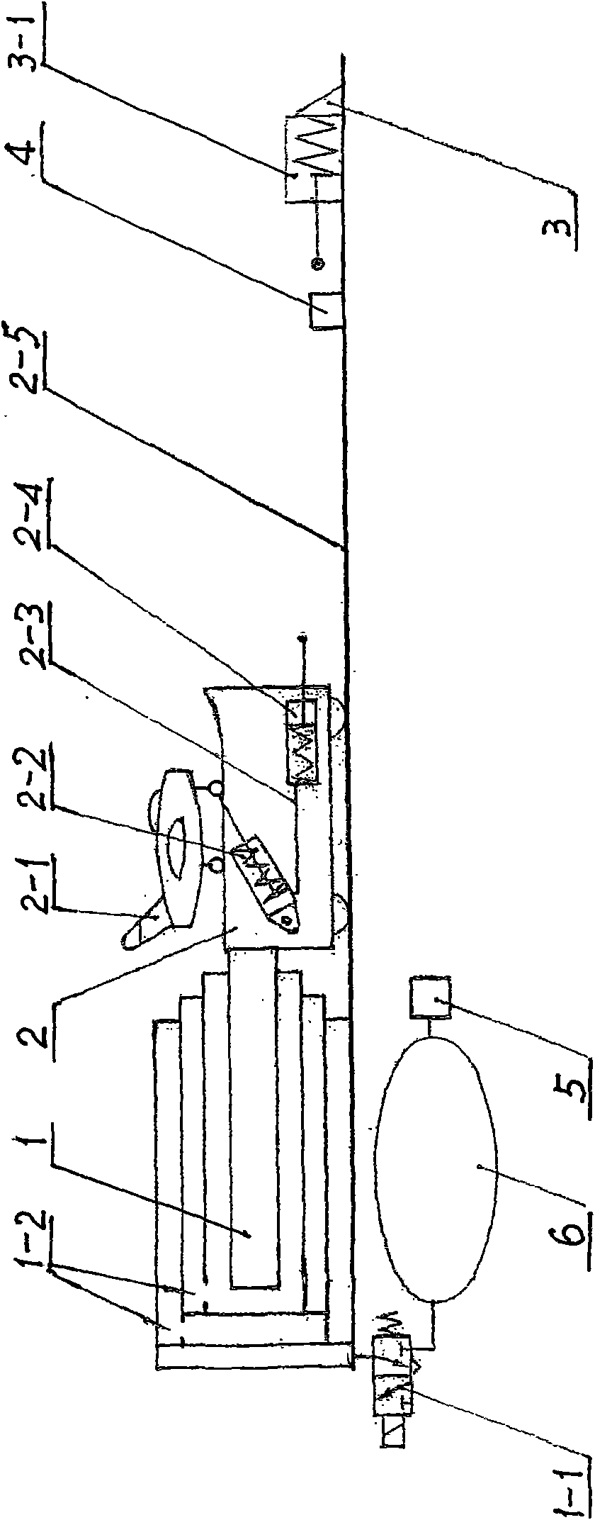
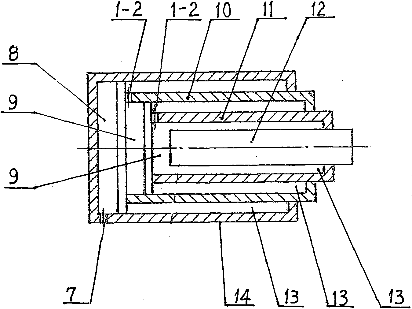
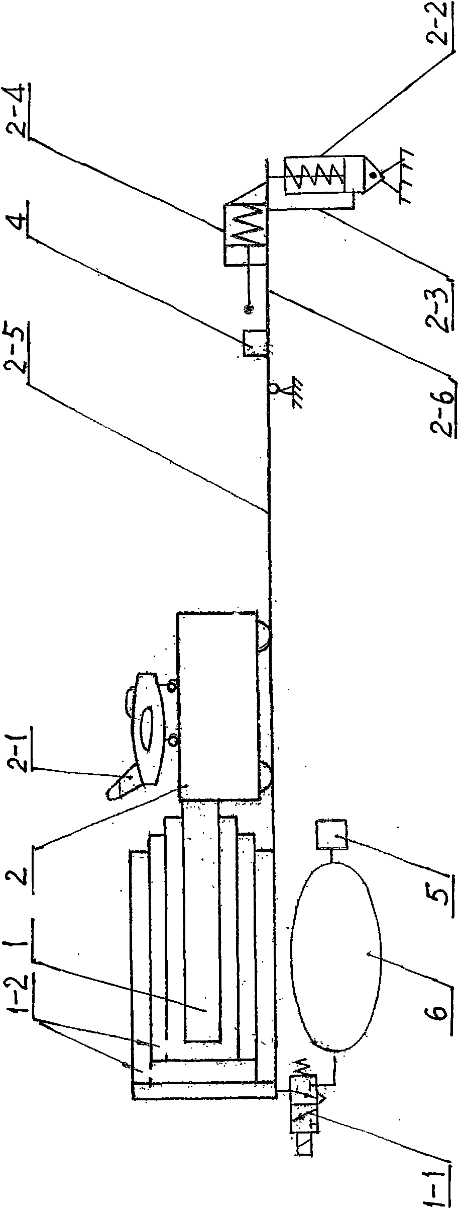
[0040] see figure 1 , figure 2 , this embodiment 1 adopts a three-stage gas-liquid fusion oil cylinder 1, a two-position three-way electromagnetic control valve 1-1, a high-energy gas source 5, a gas cylinder 6, an energy recovery pump 2-4, a jump cylinder 2-2 and a limit Buffer springs are arranged in the oil retaining cylinders 3, and damping holes 3-1 are provided in the limit oil retaining cylinders 3. Usually, according to the ejection conditions given by the superior, the digitally controlled high-energy gas source 5 collects and stores the required high-energy gas in the gas cylinder 6, and then shuts down and stands by. In its cold state with its mechanics fully closed, the catapult remains ready to fire at all times. In wartime, under the cold condition of its mechanical complete shutdown, without preparation time, the two-position three-way electromagnetic control valve 1-1 can be energized to control part of the high-energy gas in the gas cylinder 6 to enter the ...


PUM


Abstract

A aircraft carrier cold sling method and a device thereof are disclosed, which comply with the sling formula as accumulative energy swift release + high efficiency transmission = sling movement. The invention adopts gas-liquid fusion cylinder as the sling main body in cooperation with a gas cylinder and a control valve, under cold state and completely closed state of the sling machine, high energy gas collected in the gas cylinder in the sling machine enters into the gas-liquid fusion cylinder via the control valve to reach the gas reaching end to swift release energy, simultaneously pistons of all stages of the liquid reaching end of the gas-liquid fusion cylinder are pushed to carry out constant power high efficient cold sling loading. The cold sling energy recycling device adopts an energy recycling pump arranged on a reciprocate carriage, a zooming pump, and a spacing gear cylinder arranged on a guidance slide rail; or adopts a structure of hinging a movable slide rail at the front end of the guidance slide rail and arranging the energy recycling pump and the zooming pump on the movable slide rail. The aircraft carrier cold sling method and a device thereof in the invention breaks the bottleneck of passive energy storage, has strong freedom in energy accumulation and fast sling speed, can realize constant power super-high efficient transmission of enormous energy and sling in cold state won by stillness, and features simple structure, small volume, light weight, easy manufacture, small power consumption and extensive adaptability.

Description

Technical field: [0001] The invention relates to an ejection method and device in engineering mechanics, in particular to an ejection method and device in a cold state where the machine is completely closed, and can be widely used in aircraft carriers, torpedoes, missiles, accident rescue, destroyed airports, caverns, sea Drilling platforms, island liaisons, etc. Background technique: [0002] All countries regard catapults as the lifeblood of aircraft carriers, and the United States takes the lead. The reason why it will become a world problem is that a truly effective carrier ejection method has not been discovered, and existing catapults have many shortcomings: [0003] For example, the steam catapult in the United States uses open cylinder technology. The system is huge, complex, expensive, difficult to manufacture and maintain, and has an efficiency of only 4-6%. It is difficult to meet the ejection requirements of larger aircraft and has developed to the limit. [000...

Claims


Application Information

Patent Timeline
Patent Type & Authority Applications(China)
IPC IPC(8): B64F1/06
CPCB64F1/06
Inventor 胡真华胡爱武胡宣哲刘炯
Owner 胡宣哲
Learn More