
Method for reducing noise and increasing gain of low-illuminance cameras

A camera, low-light technology, applied in image communication, components of color TV, components of TV systems, etc., can solve the problems of deterioration of signal-to-noise ratio, degradation of picture quality, etc., and achieve the effect of improving sensitivity

Inactive Publication Date: 2010-03-17
SHENZHEN AIRONIX INDAL
View PDF0 Cites 6 Cited by
  • Summary
  • Abstract
  • Description
  • Claims
  • Application Information

AI Technical Summary

Problems solved by technology

[0012] The technical problem to be solved by the present invention is that for the camera system signal existing in the ultra-low illumination camera in the prior art, the original charge-coupled device output contains reset noise due to the Reset action, and the signal changes with the intensity of the light signal. The picture quality produced by the luminance signal is degraded, and the signal-to-noise ratio of the entire system is deteriorated, so that the reset noise of the entire camera system can be completely eliminated, the low-illuminance characteristics can be better improved, and the minimum illuminance of the system can be effectively improved. , to obtain an image brightness output signal with a high signal-to-noise ratio

Method used


Image

  • Method for reducing noise and increasing gain of low-illuminance cameras
  • Method for reducing noise and increasing gain of low-illuminance cameras
  • Method for reducing noise and increasing gain of low-illuminance cameras

Examples


Embodiment Construction

[0028] The present invention will be further described in detail below with reference to the drawings and specific embodiments.

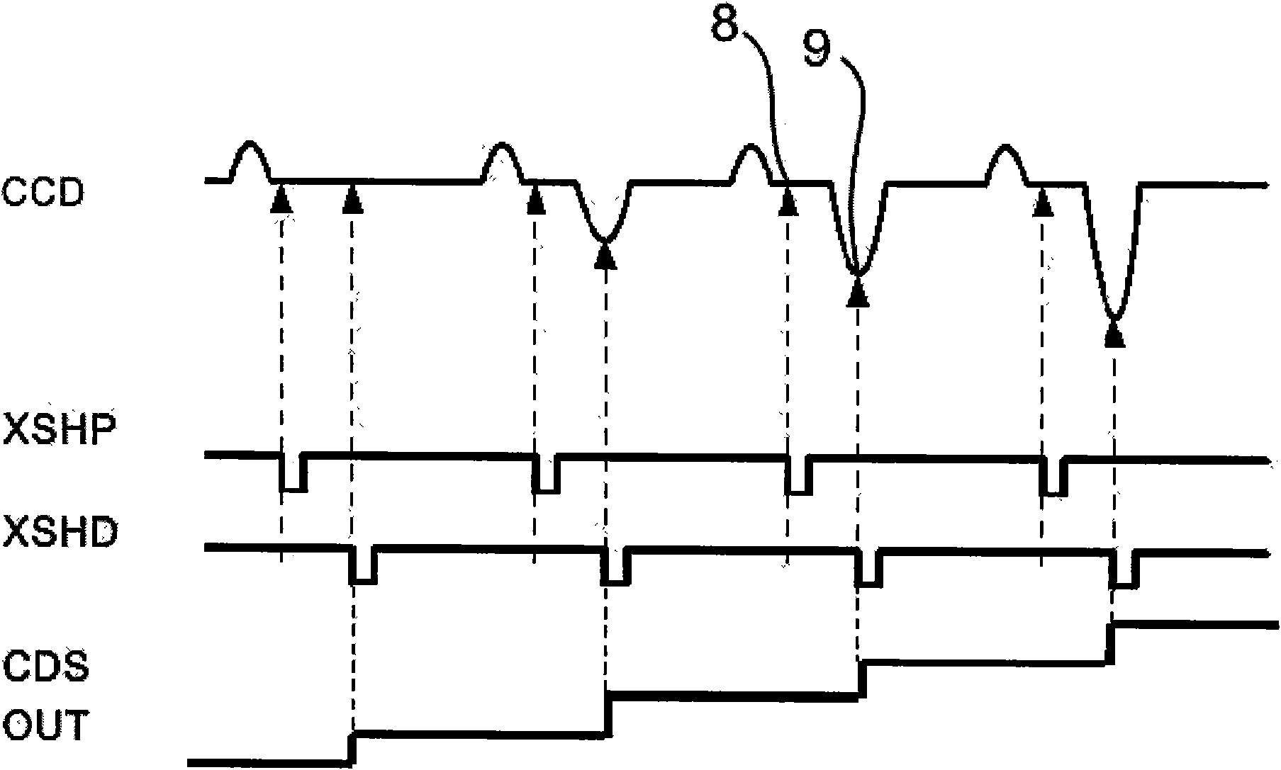
[0029] Such as Figure 1 to Figure 3 As shown, the present invention provides a method for reducing noise and increasing gain of a low-illuminance camera. The method is based on a camera using a charge-coupled image sensor 6, and the method includes:

[0030] A. Connect the relevant secondary sampling and holding circuit to the image signal output terminal of the charge coupled image sensor 6;

[0031] B. After the image signal enters the relevant secondary sampling and holding circuit, it is divided into two circuits by two capacitors, one is the upper circuit and the other is the lower circuit;

[0032] C. Connect XSHP sampling pulse 1 and XSHD sampling pulse 2 to the upper circuit and the lower circuit respectively;

[0033] D. Then connect the differential amplifier 7 at the output of the upper circuit and the lower circuit.

[0034] The image signal outp...


PUM


Abstract

The invention discloses a method for reducing noise and increasing gain of low-illuminance cameras, which applies to low-illuminance or super-sensitivity cameras. The method is based on a camera adopting a charge-coupled image sensor. The method comprises: connecting the image signal output end of the charge-coupled image sensor with a relevant secondary sampling-holding circuit and dividing imagesignals after entering the relevant secondary sampling-holding circuit into two paths of signals through two capacitors, wherein one path of signals is a top circuit, and the other path of signals isa bottom circuit; connecting XSHP sampling pulses and XSHD sampling pulses to the top circuit and the bottom circuit respectively; and connecting the output parts of the top circuit and the bottom circuit with a differential amplifier. The method has the advantage of ensuring that the low-illuminance cameras can be greatly improved in sensitivity to external light, can show optimal effects in various illumination environments, and can still clearly identify images and display real-time continuous pictures even in very dark environments.

Description

Technical field [0001] The invention relates to a method for a camera to reduce noise and increase gain, in particular to a method for a low-illuminance camera to reduce noise and increase gain when the ambient light illuminance where an object is located is low. Background technique [0002] Low-illuminance cameras have existed in the market for many years, from the earliest day and night color black-and-white switching, slow shutter image accumulation, or ultra-low-illuminance CCD, to the current popular infrared projection cameras, and there are many types . However, no one method is its shortcomings. The following introduces several kinds of low-end cameras available on the market: [0003] 1. Day and night type: [0004] Such cameras still have a certain market demand in the market. It uses the high sensitivity of black-and-white images to infrared rays. Under certain light source conditions, the image is switched from color to black-and-white by means of line switching to f...

Claims


Application Information

Patent Timeline
Patent Type & Authority Applications(China)
IPC IPC(8): H04N5/235H04N5/217H04N5/21
Inventor 葛俭
Owner SHENZHEN AIRONIX INDAL
Learn More