
Slotted core ribbon cable

A skeleton and cable technology, which is applied in the field of cables with skeletons, can solve the problems of affecting the current-carrying performance of conductors, reducing the cross-section of conductors, and easy cracking of insulating layers, etc., and achieves the effects of simple structure, reduced cross-section and long product life

Inactive Publication Date: 2010-03-17
高飞
View PDF4 Cites 42 Cited by
  • Summary
  • Abstract
  • Description
  • Claims
  • Application Information

AI Technical Summary

Problems solved by technology

Since this type of cable adopts a circular insulating layer and adopts a multi-stranded method, they have the following disadvantages: 1. It occupies a large space; 2. Due to the twisting of the insulating layer, the surface of the already thin insulating layer is easily damaged. Micro-cracks are formed, so the insulating layer is easy to crack; 3. The re-twisting of the insulating layer with conductors causes the conductors that have been stranded to be stressed for a long time, reducing the cross-section of the conductors and affecting the current-carrying performance of the conductors; 4. The conductor's Stranding requires a high-power-consuming stranding motor and a precise pitch control system; 5. Since the insulating layers are twisted together, the heat dissipation effect is poor and the current carrying capacity is weak

Method used


Image

  • Slotted core ribbon cable
  • Slotted core ribbon cable
  • Slotted core ribbon cable

Examples


Embodiment 1

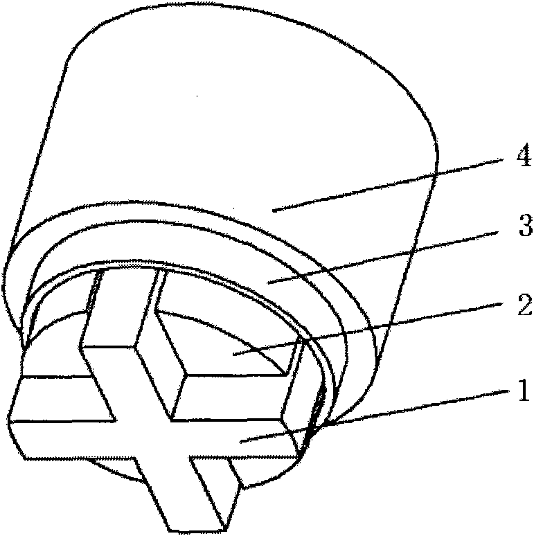
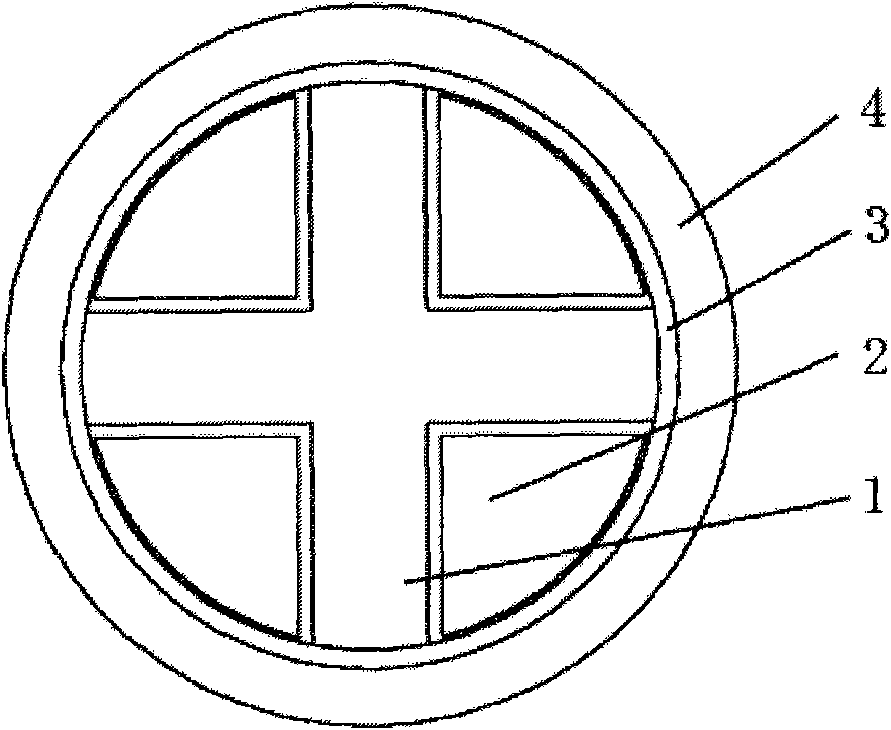
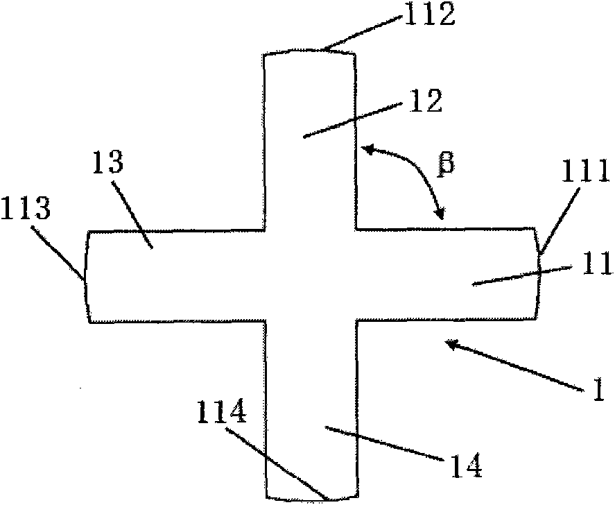
[0029] See figure 1 , figure 2 with image 3 , a skeleton cable, which includes an outer sheath 4 and a conductor 2, and the conductor 2 is located in the outer sheath 4; it is characterized in that: the outer sheath 4 also includes a skeleton 1, and the skeleton 1 separates the inside of the outer sheath into four mutual In the fan-cylindrical space that is not connected, the conductor 2 is located in the fan-cylindrical space; any two conductors do not touch each other; on the cross-section of the skeleton 1, the skeleton is composed of bone leaves (11, 12, 13, 14), and the skeleton The outer edges of the lobes are arcs (111, 112, 113, 114), and the edges of the two lobes connected to the arcs on any lobes are parallel to each other, and an angle β is formed between adjacent lobes; the value of β is 90 degrees; the arcs (111, 112, 113, 114) on the outer edge of the bone leaf are of equal curvature and the centers of the arcs coincide with each other and the lengths of the...

Embodiment 2

[0031] See Figure 4 , basically the same as the implementation example 1, the difference is that there is no protective layer 3.

Embodiment 3

[0033] See Figure 5 , basically the same as the implementation example 2, the difference is that: the skeleton 1 is also provided with a reinforcing member 5; the reinforcing member 5 is metal or non-metallic; preferably aramid yarn or glass fiber is added to a plastic rod or steel wire; the introduction of the reinforcing member , making the entire cable more resistant to stretching.


PUM

PropertyMeasurementUnit
Thicknessaaaaaaaaaa

Abstract

The invention belongs to the technical field of electric wires and cables and relates to a slotted core ribbon cable. The slotted core ribbon cable at least comprises an outer sheath (4) and conductors (2) which are positioned inside the outer sheath (4). The slotted core ribbon cable is characterized in that: the outer sheath (4) internally further comprises a slotted core ribbon (1) which divides the inside of the outer sheath into a plurality of fan-post shaped spaces which are not intercommunicated and the conductors (2) are positioned inside the fan-post shaped spaces; and any two of theconductors do not contact each other. The slotted core ribbon cable mainly solves problems of simplifying manufacturing equipment and cable structure, lowering cost, increasing carrying capacity, prolonging service life of cables, intensifying heat emission and the like. The slotted core ribbon cable has the advantages of simple structure, lower cost, more convenient use, better heat emission, stronger carrying capacity, less equipment investment and longer service life of products.

Description

[0001] On the same day when the application for the present invention was filed, the applicant filed an application for a utility model patent at the same time. technical field [0002] The invention relates to the technical field of wires and cables, in particular to a cable with a skeleton. Background technique [0003] Wires and cables are used in almost every field of industrial production and life. However, the existing cables are made by adopting a circular cable conductor, then covering the conductor with an insulating layer, and then allowing a plurality of insulating layers to be twisted and then placed in the sheath to complete the production. Since this type of cable adopts a circular insulating layer and adopts a multi-stranded method, they have the following disadvantages: 1. It occupies a large space; 2. Due to the twisting of the insulating layer, the surface of the already thin insulating layer is easily damaged. Micro-cracks are formed, so the insulating la...

Claims


Application Information

Patent Timeline
IPC IPC(8): H01B7/42
Inventor 龚利芬
Owner 高飞
Learn More