Eureka AIR delivers breakthrough ideas for toughest innovation challenges, trusted by R&D personnel around the world.

Mixer for a continuous flow reactor, method of forming such a mixer, and method of operating such a reactor

A technology of mixers and reactors, applied in the direction of mixing methods, fluid mixers, chemical instruments and methods, etc., can solve problems such as low efficiency

Active Publication Date: 2010-03-03
DOW GLOBAL TECH LLC
View PDF4 Cites 11 Cited by
  • Summary
  • Abstract
  • Description
  • Claims
  • Application Information

AI Technical Summary

Problems solved by technology

However, the coaxial approach is less efficient for rapid mixing between the two fluids than when the fluids meet at an angle

Method used


Image

  • Mixer for a continuous flow reactor, method of forming such a mixer, and method of operating such a reactor
  • Mixer for a continuous flow reactor, method of forming such a mixer, and method of operating such a reactor
  • Mixer for a continuous flow reactor, method of forming such a mixer, and method of operating such a reactor

Examples


Embodiment Construction

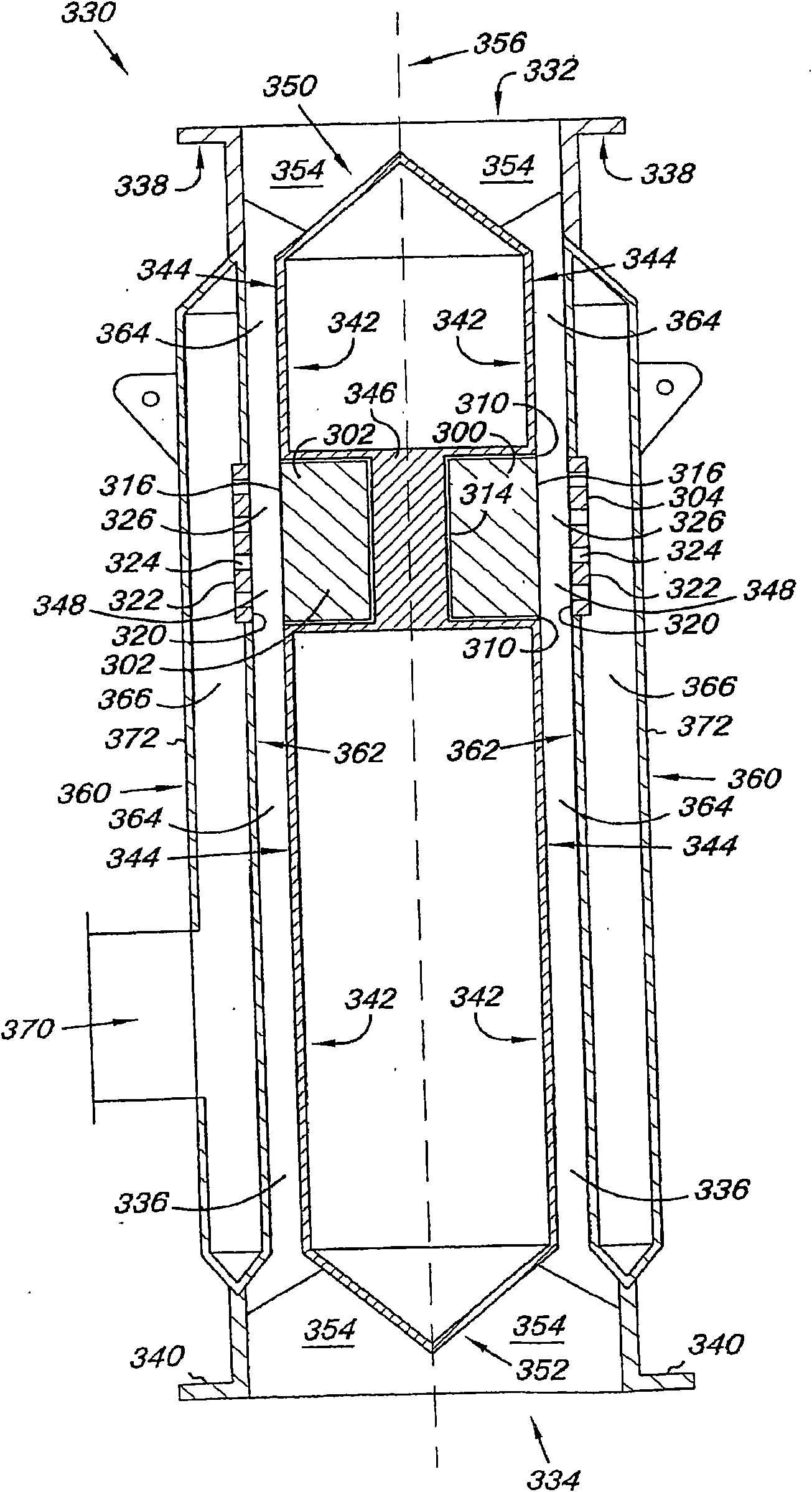
[0013] Embodiments of the present disclosure include mixers for continuous flow reactors that provide rapid mixing with minimal backmixing, thereby helping to reduce the formation of unwanted by-products. To achieve rapid mixing, the mixer includes channels with constant width dimensions, and orifices leading to the channels. Embodiments of the mixers of the present disclosure can divide a first reactant stream through an orifice of the mixer and inject it into a second reactant stream flowing through the channels of the mixer. Splitting the first reactant stream and injecting it into the second reactant stream can help minimize the mixing length of the reagents (ie, allow the streams to mix in a short space).

[0014] For various embodiments, the relative flows of the first and second reactant streams may depend on the reactant concentrations and the desired stoichiometry of the reaction(s). In such cases, the number and size (ie, degree of separation) of the orifices may be...


PUM


Abstract

A mixer (100) for a continuous flow reactor (330) and methods for forming the mixer and the operation thereof. The mixer allows for segmentation of a primary reactant flow through a plurality of ports (124) into many smaller flows that are injected as jets into a secondary reactant flow in channels of the mixer. The channel (126) has a constant width dimension to enhance even flow distribution and local, turbulence of the primary and secondary reactant flows. The constant width dimension of the channel and the size and number of the ports of the mixer can be configured to ensure the primary reactant flow injected into the channel directly impinges on a surface (116) of the channel that is opposite the injection point at normal operating conditions.

Description

technical field [0001] The present disclosure relates generally to mixers, in particular to mixers for continuous flow reactors. Background technique [0002] In many chemical processes, turbulent flow facilitates chemical reactions, heat transfer operations, mixing and combustion processes. Effective use of turbulent flow can increase interfacial contact of reagents, thereby reducing reaction times and the cost and time of preparing many chemicals. [0003] Many existing chemical process plants utilize tubular reactors to continuously mix and react two or more reagents under turbulent diffusion conditions (Re > 2000). Reagents can be injected into the tubular reactor in a number of different ways. One approach is to introduce the reagents such that they meet at an angle (eg 90 degrees). Another approach is to bring the reagents together on-axis. However, the coaxial approach is less efficient in terms of rapid mixing between the two fluids than when the fluids meet a...

Claims


Application Information

Patent Timeline
Patent Type & Authority Applications(China)
IPC IPC(8): B01F3/04B01F3/08B01F5/04B01J19/24
CPCB01F5/0475B01J19/2405B01F5/0463B01F15/00844B01F3/0865B01F5/048B01F2215/0036B01F3/0446B01F2005/0017Y10T29/49826B01F23/232B01F23/451B01F2025/913B01F25/31331B01F25/3142B01F25/31423B01F35/512B01F2101/2204B01J19/24B01F23/20B01F23/40B01F25/30B01F25/27B23P19/00
Inventor 吉恩·W·巴赫曼雷蒙德·M·琼斯迈克尔·D·克勒特查尔斯·W·利普马克·J·巴特尔布雷迪·J·库默斯斯科特·J·戴格尔史蒂夫·F·扬达
Owner DOW GLOBAL TECH LLC
Why Eureka
Eureka Blog
Learn More