Rectifier tube real-time control circuit and light load control method thereof

A technology for controlling circuits and rectifier tubes, which is applied to electrical components, high-efficiency power electronic conversion, and conversion of AC power input to DC power output. It can solve problems such as increasing asynchronous rectification time and reducing rectification efficiency, so as to avoid instability, Improved rectification efficiency and high noise immunity

Active Publication Date: 2010-03-03
CHENGDU MONOLITHIC POWER SYST
View PDF0 Cites 22 Cited by
  • Summary
  • Abstract
  • Description
  • Claims
  • Application Information

AI Technical Summary

Problems solved by technology

In addition, in this drive mode, the gate drive voltage V GS Control the rectifier tube to work in two states of off or saturated conduction. When the load is low, in order to prevent false triggering, the rectifier tube often interrupts synchronous rectification in advance in one switching cycle, correspondingly increases the time of asynchronous rectification, and reduces the rectification efficiency.

Method used


Image

  • Rectifier tube real-time control circuit and light load control method thereof
  • Rectifier tube real-time control circuit and light load control method thereof
  • Rectifier tube real-time control circuit and light load control method thereof

Examples


Embodiment Construction

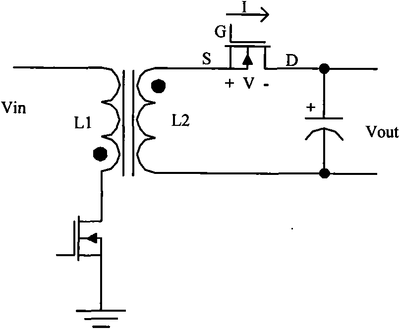
[0025] image 3 Shows the real-time synchronous driving mode of the secondary side synchronous rectifier corresponding to the present invention. At time t1, V GS Set high, the synchronous rectifier tube is turned on. At time t2, as the current drops V DS Slowly rise to V 1 , V GS As the current decreases, it gradually decreases, making V DS Stay at V 1 . Until V GS The reduction of V cannot stop V DS When the rise of V DS Down to V 2 , Turn off the synchronous rectifier tube. In this synchronous drive mode, the gate drive voltage includes a linear and real-time change phase to maintain V DS Constant, this method is called real-time synchronous rectification. Real-time synchronous rectification can realize the fast turn-off of the switch and reduce the switching loss. At the same time, the switch can maintain synchronous rectification for a long time when the load is light.

[0026] In this driving mode, the smaller the load, the V GS The earlier it drops. In view of th...


PUM


Abstract

The invention discloses a rectifier tube control circuit and a light load control method. When a rectifier tube is synchronously rectified, the gate drive voltage (VGS) of the rectifier tube is detected after the conducted preset time delay; if the VGS is less than a reference value, the rectifier tube is proved to have a light load; and if the VGS is more than a reference value, the rectifier tube is proved to have a heavy load. In one implementation mode, after the light load is continuously detected and lasts for a preset time, the synchronous rectifier is stopped; the synchronous rectifieris restarted every a plurality of periods and the light load or the heavy load is judged. In the other implementation mode, if the load is indicated for a plurality of continuous periods and lasts for a preset time, the synchronous rectifier is stopped; and when the rectifier tube is in non-synchronous rectifier, drain-source voltage (VDS) of the rectifier tube is detected in preset time delay after a crystal diode is conducted, if the VDS is less than the reference value, the synchronous rectifier is started at the next period. The invention improves the rectifier efficiency, effectively avoids the unstability in a critical state and also improves the noise resisting performance.

Description

Technical field [0001] The invention relates to an isolated voltage converter, in particular to the control of the voltage converter to stop synchronous rectification when the load is light. Background technique [0002] There are currently two types of secondary rectification schemes for flyback DC-DC converters, one is non-synchronous rectification (such as Figure 1A Shown), the other is synchronous rectification (such as Figure 1B Shown). Asynchronous rectification is conducted through a diode. Synchronous rectification uses a gate drive signal to control the on and off of the synchronous rectifier. The synchronous rectifier generally uses a MOSFET. Figure 1C The curve shows the resistance characteristics of diodes and synchronous rectifiers. In practical applications, the operating range of the low-power flyback DC-DC converter is in the shaded range. In this interval, the synchronous rectifier resistance characteristic curve 11 is located below the diode resistance charac...

Claims


Application Information

Patent Timeline
IPC IPC(8): H02M7/12H02M7/217
CPCH02M3/158Y02B70/16Y02B70/1475H02M2001/0032H02M3/33592H02M1/0032Y02B70/10
Inventor 张军明任远程缪磊毛昭祺
Owner CHENGDU MONOLITHIC POWER SYST
Why Eureka
Try Eureka