
Overflow glue removing mechanism and method thereof

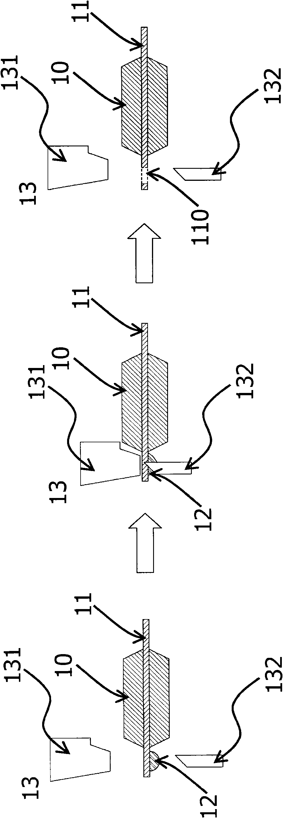
A technology of overflowing glue and chips, which is applied in the direction of electrical components, semiconductor/solid-state device manufacturing, circuits, etc., and can solve problems such as shrinkage of the connection area, breakage, and drop of the molded chip 10

Inactive Publication Date: 2010-03-03
CHIPMOS TECH INC
View PDF0 Cites 3 Cited by
  • Summary
  • Abstract
  • Description
  • Claims
  • Application Information

AI Technical Summary

Problems solved by technology

[0004] Due to the relative movement of the upper and lower movable parts 131, 132 of the cutter device 13 to break through the local lead frame 11 of the molded chip 10 to form a through hole 110 on the lead frame 11, although the overflow glue 12 can be removed from the lead frame 11 However, this method of using the cutter device 13 to penetrate the lead frame 11 makes the joint area between the molded chip 10 and the lead frame 11 smaller and may cause fractures, making the molded chip 10 easy to separate from the connected lead frame 11 while falling

Method used


Image

  • Overflow glue removing mechanism and method thereof
  • Overflow glue removing mechanism and method thereof
  • Overflow glue removing mechanism and method thereof

Examples


Embodiment Construction

[0013] Since the present invention discloses a glue overflow removal mechanism and its method, which are used to remove the glue overflow on the lead frame of the molded chip, the manufacturing principle and packaging and testing method of the molded chip are already common knowledge in the relevant technical field The reader can understand it, so the following description will not make a complete description. At the same time, the drawings compared below are schematic structural representations related to the features of the present invention, and are not and need not be completely drawn according to actual dimensions, and will be described here first.

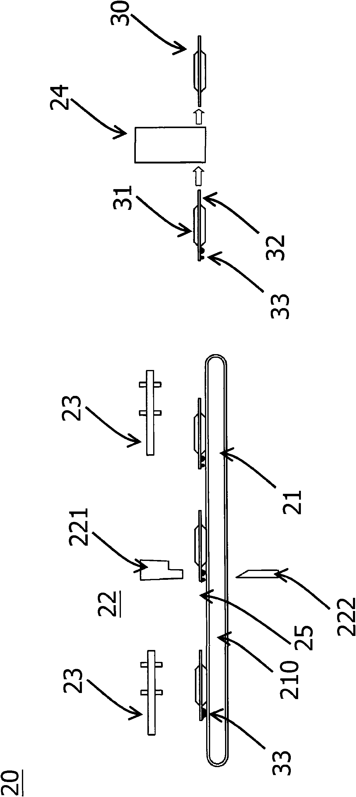
[0014] First please refer to figure 2 , the figure shows the first preferred embodiment of the present invention to remove the glue overflow mechanism 20, which is mainly used to remove the overflow glue on the lead frame of the molded chip, wherein the molded chip 30 includes a chip body 31, Connect the lead frame 32 of th...


PUM


Abstract

The invention discloses an overflow glue removing mechanism comprising a transmission device and a cutter device, wherein the transmission device is used for carrying and transmitting a plurality of mould sealing chips to a specific position of the transmission device; and the cutter device is arranged in the specific position for damaging the connection of overflow glue of the mould sealing chipsand a conducting wire rack. The overflow glue removing mechanism has the advantages that the cutter device also comprises an upper movable piece and a lower movable piece; when the mould sealing chips are transmitted between the upper movable piece and the lower movable piece by the transmission device, the lower movable piece is in contact with the overflow glue to damage the connection of the overflow glue and the conducing wire rack by the opposite movement of the upper movable piece and the lower movable piece, thereby a hole is formed between the overflow glue and the conducting wire rack, and the lower movable piece and the upper movable piece move to a position end point due to the opposite movement to form a gap.

Description

technical field [0001] The invention relates to a mechanism and method for removing glue overflow, in particular to a mechanism and method for removing glue overflow from a lead frame of a molded chip. Background technique [0002] In the past, in the chip packaging process of semiconductors, when multiple chips on a lead frame were molded, the chips on the lead frame were still connected to each other through the lead frame. There is a small amount of mold flash in the vicinity and around the molded chip, and the overflowed glue usually adheres to the lead frame around the molded chip. When the mold flash is too thick, it cannot be removed by the subsequent flushing process , resulting in the subsequent molding of each molded chip, the overflow tape will be accidentally applied to the pins of the molded finished products of each molded chip to cause product contamination, which will lead to bridging or false soldering when the subsequent molded chips are put on the board. ...

Claims


Application Information

Patent Timeline
IPC IPC(8): H01L21/56B29C37/00
Inventor 郑阿宗
Owner CHIPMOS TECH INC
Learn More