Fuel cell system

A fuel cell system and fuel cell technology, applied in the direction of fuel cells, fuel cell additives, solid electrolyte fuel cells, etc., can solve environmental problems and other problems

Active Publication Date: 2010-02-24
TOYOTA JIDOSHA KK
View PDF1 Cites 7 Cited by
  • Summary
  • Abstract
  • Description
  • Claims
  • Application Information

AI Technical Summary

Problems solved by technology

However, it is not good for the environment to discharge the hydrogen-containing oxidation waste gas directly into the atmosphere.

Method used


Image

  • Fuel cell system
  • Fuel cell system
  • Fuel cell system

Examples


Embodiment Construction

[0034] A fuel cell system according to a preferred embodiment of the present invention will be described below with reference to the drawings.

[0035] Such as figure 1 As shown, the fuel cell system 1 has a fuel cell 2 , an oxidizing gas piping system 3 , a fuel gas piping system 4 , a power system 6 , and a control device 7 . The fuel cell system 1 can be mounted on a vehicle 100, and of course not only the vehicle 100, but also can be applied to various mobile bodies (such as ships, airplanes, robots, etc.) and stationary power sources.

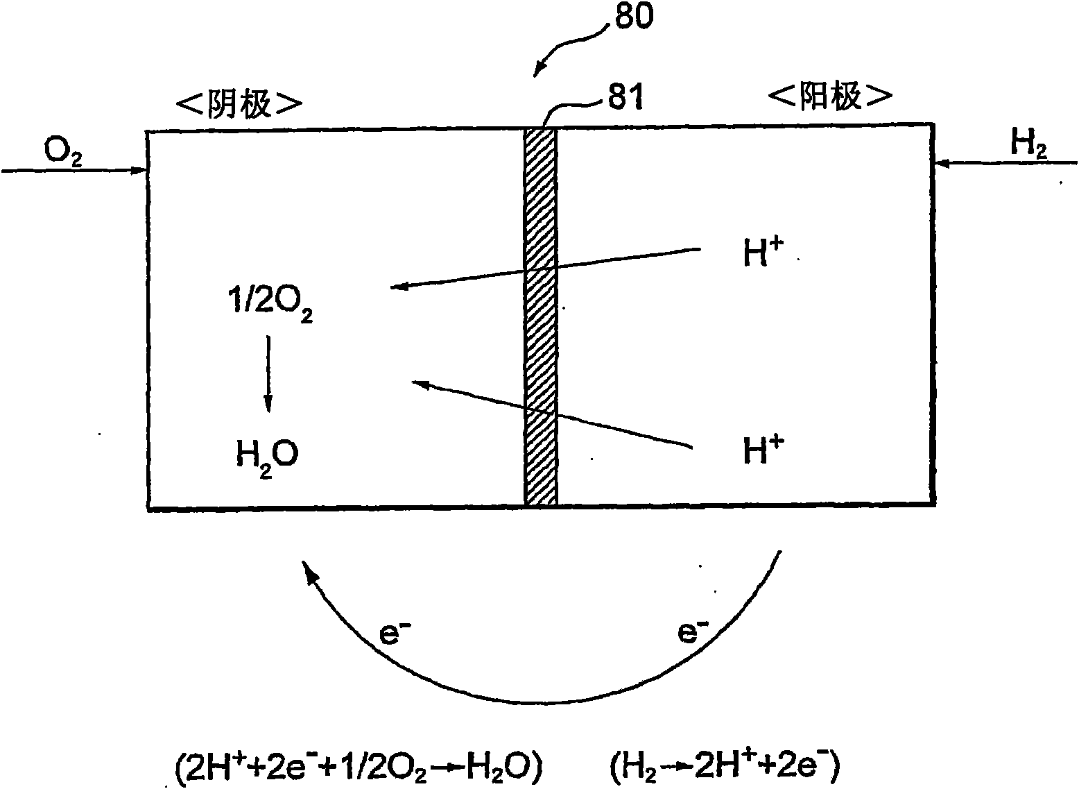
[0036] The fuel cell 2 has a stack structure in which a plurality of single cells are stacked. A solid polymer electrolyte type unit cell has an air electrode (cathode) on one side of the electrolyte composed of an ion exchange membrane, a fuel electrode (anode) on the other side, and further has an electrode sandwiched from both sides. A pair of separators holding the air electrode and the fuel electrode. The oxidizing gas is supplied ...


PUM


Abstract

It is possible to provide a fuel cell system which can control an output current of a fuel cell even if an error occurs in control of splitting a flow of an oxidizing gas. The fuel cell system includes a fuel cell and a feed device for transmitting the oxidizing gas under a pressure to the fuel cell. A feed channel is connected to a discharge channel by a bypass channel so that the oxidizing gas flows while bypassing the fuel cell. The system includes: a pressure adjusting valve which adjusts the split flow of the oxidizing gas to the bypass channel and the fuel cell; and a bypass valve. Whenthe pressure adjusting valve or the bypass valve has failed, a control unit stops the control of the output current of the fuel cell by control of the pressure adjusting valve and switches the controlto a control of the output current of the fuel cell by control of the feed device.

Description

technical field [0001] The present invention relates to a fuel cell system in which oxidizing gas can bypass the fuel cell. Background technique [0002] A fuel cell mounted on a fuel cell vehicle or the like generates electric power through a chemical reaction between hydrogen in a fuel gas supplied to an anode and oxygen in an oxidizing gas supplied to a cathode. Generally, the fuel off-gas discharged from the fuel cell passes through the hydrogen diluter, and is discharged into the atmosphere with the hydrogen concentration reduced. On the other hand, the oxidized off-gas discharged from the fuel cell is directly discharged into the atmosphere. [0003] However, when the fuel cell is operated with low power generation efficiency in order to rapidly raise the temperature of the fuel cell, hydrogen (mainly pumped hydrogen) may be generated in the cathode. Therefore, hydrogen will be contained in the oxidation exhaust gas. However, it is not good for the environment to di...

Claims


Application Information

Patent Timeline
Patent Type & Authority Applications(China)
IPC IPC(8): H01M8/04H01M8/00H01M8/10
CPCH01M8/04686H01M8/04089H01M8/0441H01M8/0491H01M8/04365Y02E60/50H01M8/04753H01M8/04559H01M8/04589
Inventor 真锅晃太小川朋也
Owner TOYOTA JIDOSHA KK
Why Eureka
Try Eureka