
Manual/automatic gearbox for mutually floating gear

An automatic transmission and gear technology, applied in the field of transmission systems, can solve the problems of high manufacturing precision, high production cost, low transmission efficiency, etc., and achieve the effects of low manufacturing cost, low maintenance cost and high transmission efficiency

Inactive Publication Date: 2010-02-24
杜良智
View PDF0 Cites 2 Cited by
  • Summary
  • Abstract
  • Description
  • Claims
  • Application Information

AI Technical Summary

Problems solved by technology

[0002] In the background technology, the shifting timing of the existing motor vehicle manual transmission is inaccurate, the shifting time is long, the engine cannot work continuously when shifting, the shifting distracts the driver's energy and increases the driver's labor intensity, and the manual transmission is limited by the shifting operating system. Its gears cannot be designed as six gears, seven gears, eight gears or even more, and the power and economy of the engine cannot be improved.
[0003] Existing automatic transmissions for motor vehicles have complex structures, high manufacturing precision, difficult maintenance, high production costs, low transmission efficiency, untimely and accurate gear shifting, and combined engine braking cannot be used in rain, snow, ice or when the vehicle braking system fails, reducing The safety of the car's driving and braking is compromised, the power and economy of the engine are not high, and more importantly, it has not been manufactured in China so far.

Method used


Image

  • Manual/automatic gearbox for mutually floating gear
  • Manual/automatic gearbox for mutually floating gear
  • Manual/automatic gearbox for mutually floating gear

Examples


Embodiment Construction

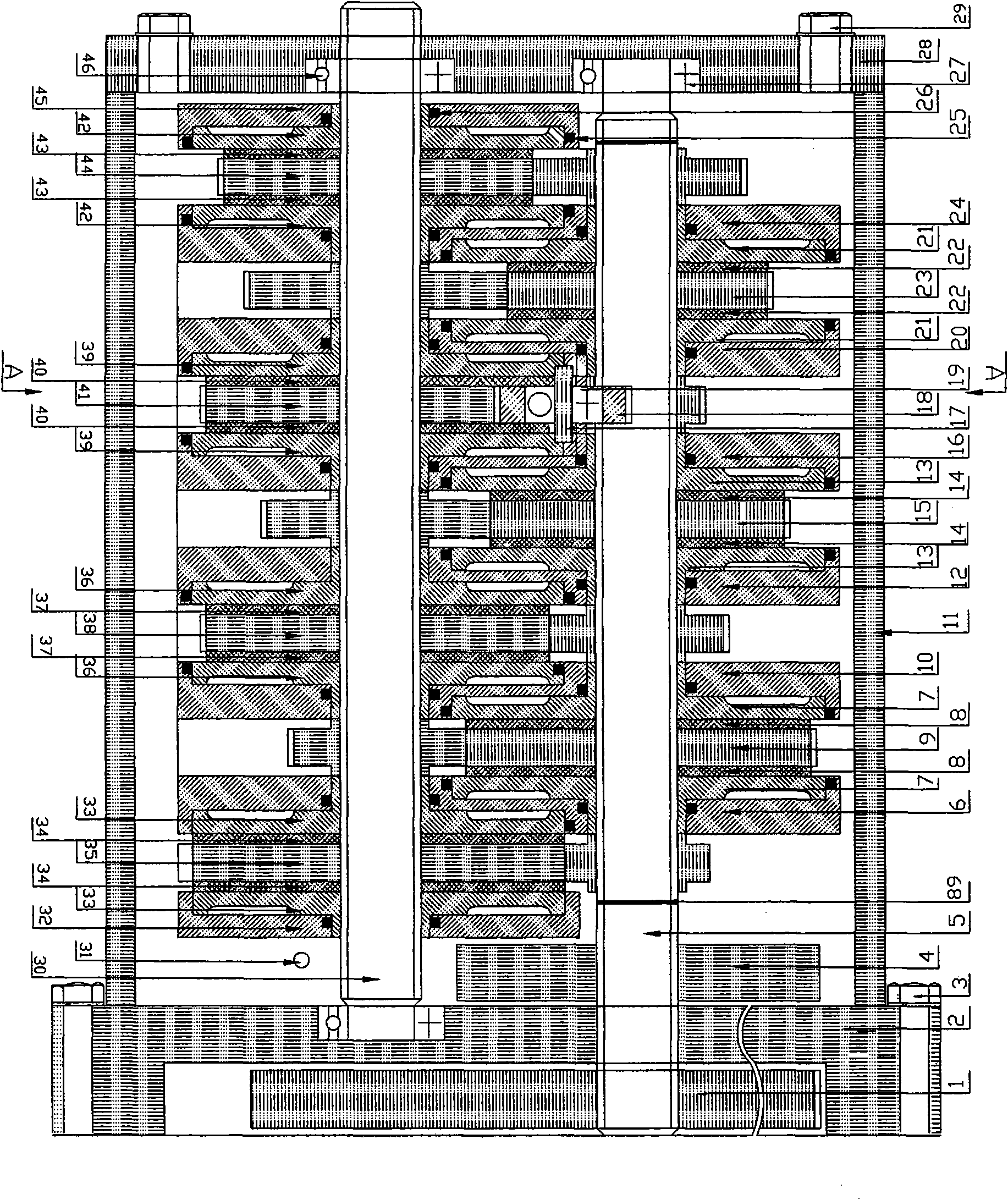
[0039] In the present invention, there are two pistons floating in the clutch of each gear position of the mutually floating gear, and the speed change is realized by the main and secondary gears in the speed change mechanism, and the gear shift is controlled by hand or automatically selected by the hydraulic electronic control system. , manual shift and automatic shift are two independent shift systems.

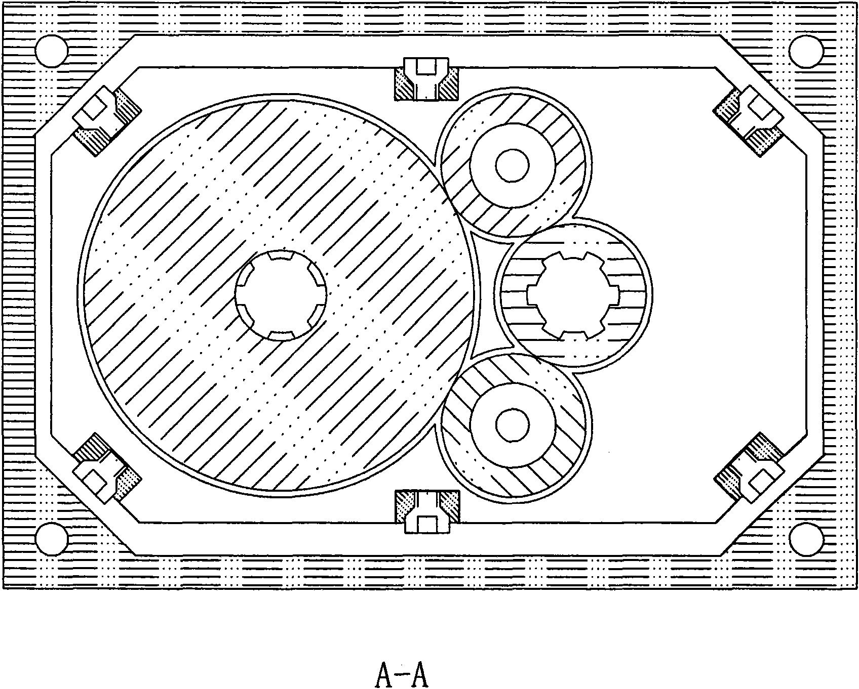
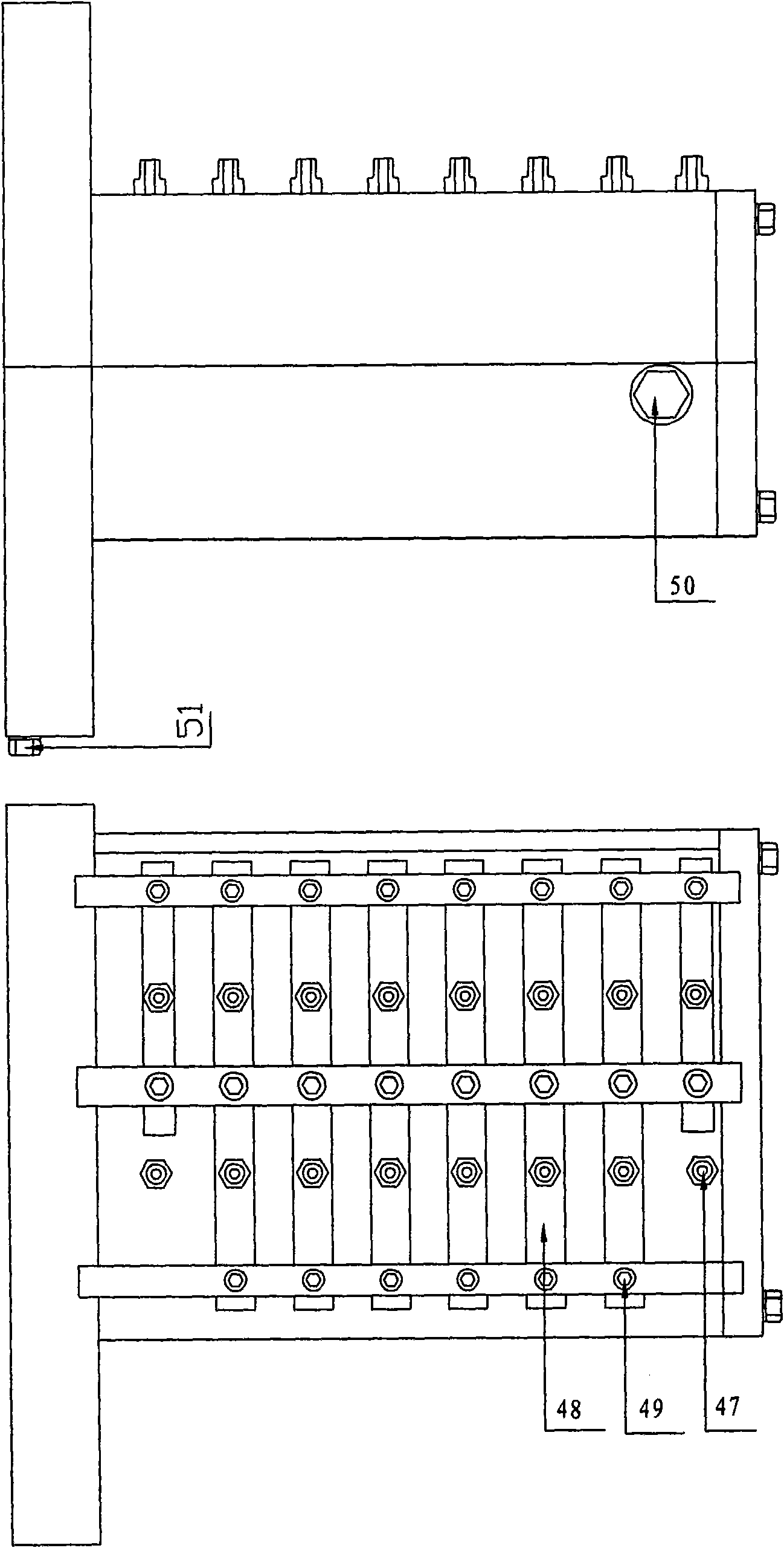
[0040] see figure 1 , figure 2 and image 3 , Interfloating gear manual and automatic transmissions are mainly composed of basic parts, gear transmission mechanisms, clutch mechanisms and hydraulic electronic control systems (stepping motor speedometer hydraulic control systems). The basic parts are mainly composed of flywheel 1, flywheel housing and rubber pad 2, gearbox body and gearbox body rubber pad 11, gearbox rear cover and gearbox rear cover rubber pad 28, 6-M12x65 bolts, diameter 12 flat pads and spring pads 3. It consists of 4-M10X317 bolts, flat washers with a...


PUM


Abstract

The invention relates to a manual / automatic gearbox for mutually floating gear, which is characterized in that the structure is simple, visualized and compact; the manufacturing cost is low; the work is reliable; the transmission efficiency is high; the maintenance is convenient and the multi-pole shift can be realized. The invention comprises a gear shift, a clutch mechanism and a hydraulic electronic control system, wherein the gear shift comprises a flywheel which is fixedly connected to an input shaft by a spline. The input shaft comprises an outer spline and a locating jump ring. By a spline, the input shaft is respectively connected to a first-speed master gear, a second-speed master gear, a third-speed master gear, a backward master gear, a sixth-speed clutch piston, a fifth-speed clutch piston and a fourth-speed clutch piston. An output shaft comprises an outer spline and a locating jump ring. By a spline, the output shaft is respectively connected to a sixth-speed secondary gear, a fifth-speed secondary gear, a fourth-speed secondary gear and a first-speed clutch.

Description

1. Technical field: [0001] The present invention relates to a transmission, in particular to a manual and automatic transmission with inter-floating gears, to a manual transmission for a motor vehicle, an automatic transmission for a motor vehicle, a large truck, a large bus, a train, a ship, a warship, a tank, a large tractor, The speed change system of large machine tools and all equipment that needs speed change. 2. Background technology: [0002] In the background technology, the shifting timing of the existing motor vehicle manual transmission is inaccurate, the shifting time is long, the engine cannot work continuously when shifting, the shifting distracts the driver's energy and increases the driver's labor intensity, and the manual transmission is limited by the shifting operating system. Its stalls can't be designed into six gears, seven gears, eight gears or even more, and the power and economy of the engine cannot be improved. [0003] Existing automatic transmis...

Claims


Application Information

Patent Timeline
IPC IPC(8): F16H63/02
Inventor 杜良智
Owner 杜良智
Learn More