Cyclone separator, cyclone separation device and vacuum cleaner having cyclone separation device

A technology of cyclone separation device and cyclone separator, which is applied in the direction of vacuum cleaners, cyclone devices, and devices in which the axial direction of the cyclone can be reversed, etc., to achieve the effects of improved separation efficiency, high separation efficiency, and low power loss

Active Publication Date: 2013-04-03
ECOVACS ROBOTICS (SUZHOU ) CO LTD
View PDF3 Cites 0 Cited by
  • Summary
  • Abstract
  • Description
  • Claims
  • Application Information

AI Technical Summary

Problems solved by technology

There is a problem here: when the gas-solid separation of the airflow in the first cyclone unit is insufficient, the airflow entrained with dust particles directly enters the second cyclone unit, and the airflow is entrained in the case of incomplete gas-solid separation in the second cyclone unit. The fine particles of impurities will leave the cyclone and be released into the atmosphere by the electric fan

Method used


Image

  • Cyclone separator, cyclone separation device and vacuum cleaner having cyclone separation device
  • Cyclone separator, cyclone separation device and vacuum cleaner having cyclone separation device
  • Cyclone separator, cyclone separation device and vacuum cleaner having cyclone separation device

Examples


Embodiment Construction

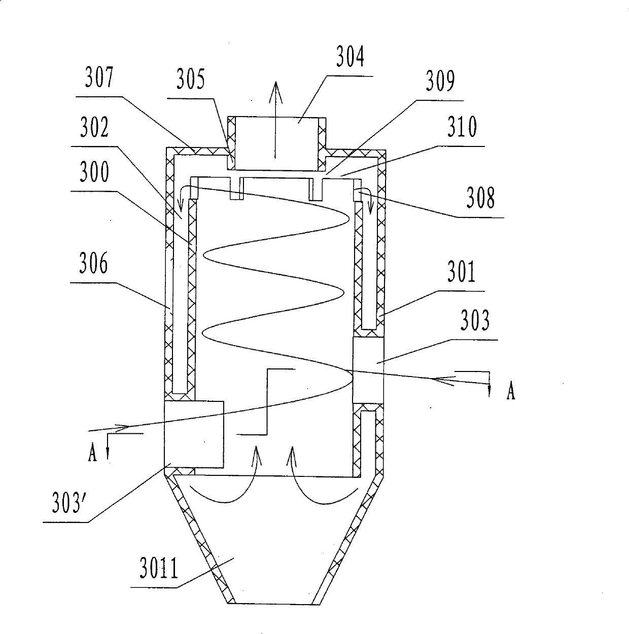
[0050] figure 2 It is the structural representation of the cyclone separator of the present invention, as figure 2 As shown, the present invention provides a cyclone separator, which comprises an inner cylinder 300 and an outer cylinder 301, an annular gap 302 is formed between the outer wall of the inner cylinder 300 and the inner wall of the outer cylinder 301, and the inner cylinder 300 The lower end of the outer cylinder 301 is an open end, the lower end of the outer cylinder 301 is closed, an air inlet 303 is set on the wall of the outer cylinder, an air outlet 304 is provided at the upper end of the outer cylinder 301, and a return section is provided between the upper end of the inner cylinder 300 and the air outlet 304 . The airflow enters the separator from the air inlet 303, part of the airflow after primary separation is discharged from the air outlet 304, and the other part is separated from the return part through the annular gap 302 for secondary separation, a...


PUM


Abstract

A cyclone is provided. The cyclone includes an inner cylinder (300) and an outer cylinder (301). An annular space (302) is formed between the outerwall of the inner cylinder (300) and the innerwall of the outer cylinder (301). The lower end of the inner cylinder (300) is open, and the lower end of the outer cylinder (301) is close. There is an air inlet (303) in the wall of the outer cylinder (301). There is an air outlet (304) on the upper end of the outer cylinder (301). A circumfluence part is provided between the upper end of the inner cylinder (300) and the air outlet (304). Air flow enters the cyclone tangentially through the air inlet (303) on the lower end of the outer cylinder (301). A part of separated air flow is discharged through the air outlet (304), another part of separated air flow is separated again from the circumfluence part through the annular space (302). The separated circumfluence flow enters the inner cylinder (300) and mixes with new ingoing flow so as to be separated once more.

Description

technical field [0001] The invention relates to a cyclone separator, a cyclone separation device equipped with the cyclone separator and a vacuum cleaner thereof. Background technique [0002] The vacuum cleaner uses its built-in motor to drive the fan to generate negative pressure for dust removal. It will not fly dust during operation and use, and can absorb dust that is generally difficult to remove in the gaps and on the carpet. It is easy to use and easy to operate. It is widely used For home and public places. [0003] With the improvement of people's living standards, the awareness of environmental protection is gradually increasing. People's requirements for vacuum cleaners not only meet the function of effective dust collection, but also consider comprehensive factors such as service life, noise, and dust collection efficiency. Thus, the vacuum cleaner with the cyclone separation device came into being and has been generally recognized by people. [0004] The pate...

Claims


Application Information

Patent Timeline
Patent Type & Authority Patents(China)
IPC IPC(8): A47L9/16A47L5/12
CPCB04C5/08B04C7/00A47L9/1608
Inventor 郑德钦
Owner ECOVACS ROBOTICS (SUZHOU ) CO LTD
Why Eureka
Try Eureka