
Zero-backpressure electronically-controlled diesel injector driven by magnetostrictive component

A diesel fuel injector and magnetostrictive technology, applied in the direction of engine components, machines/engines, fuel injection devices, etc., can solve problems such as difficulty in responding to injection frequency, and achieve the effects of improved technical indicators, low cost, and convenient processing and manufacturing

Inactive Publication Date: 2010-02-17
柳州福尔曼汽车电子有限公司
View PDF1 Cites 5 Cited by
  • Summary
  • Abstract
  • Description
  • Claims
  • Application Information

AI Technical Summary

Problems solved by technology

[0002] At present, the fuel supply system of the common rail electronically controlled diesel engine uses an electromagnetic injector to inject high-pressure diesel into the cylinder. Since the electromagnetic coil of the electromagnetic injector has a certain degree of inductance when it works, it is difficult to respond to the requirements of higher injection frequency. , which limits the development of diesel engines in the direction of lower fuel consumption, cleaner emissions, and lower noise. Moreover, the two-position three-way valve used in the injector of the electronically controlled injector has a large force due to back pressure. Requires greater control to control

Method used


Image

  • Zero-backpressure electronically-controlled diesel injector driven by magnetostrictive component
  • Zero-backpressure electronically-controlled diesel injector driven by magnetostrictive component
  • Zero-backpressure electronically-controlled diesel injector driven by magnetostrictive component

Examples


Embodiment 1

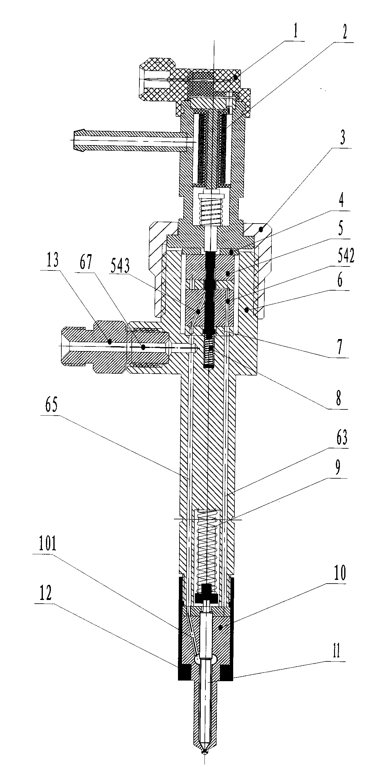
[0042] A non-backpressure electronically controlled diesel fuel injector driven by a magnetostrictive element, including a fuel injector housing 6 with an oil inlet passage and an oil return passage, a nut sleeve 12, a magnetostrictive driver 2, and a two-position non-backpressure Three-way valve 5, lock nut 3, adjusting gasket 4, transition block 7, return spring 8, pressure spring 9 and injector assembly 10 are installed back in sequence in the injector housing 6 along the axial direction Position spring 8, transition block 7, two-position three-way valve without back pressure 5, adjusting gasket 4, lock nut 3, magnetostrictive driver 2, and the pressure spring 9 and the fuel injection nozzle coupler are sequentially installed in the nut sleeve 12 Part 10, the upper and lower end surfaces of the injector housing 6, the transition block 7, the two-position three-way valve 5 without back pressure, the two end surfaces of the adjusting gasket 4, and the lower end surface of the ...


PUM


Abstract

The invention discloses a zero-backpressure electronically-controlled diesel injector driven by a magnetostrictive component, which comprises a diesel injector shell provided with a diesel inlet passage and a diesel return passage, a nut cap, a magnetostrictive actuator, a zero-backpressure two-position three-way valve, a lock nut, an adjusting shim, a transition block, a return spring, a pressure spring and injection nozzle matching parts. The return spring, the transition block, the zero-backpressure two-position three-way valve, the adjusting shim, the lock nut, and the magnetostrictive actuator are orderly arranged in the diesel injector shell along the axial direction. The pressure spring and the injection nozzle matching parts are orderly arranged in the nut cap. The upper end surface and the lower end surface of the diesel injector shell, the two end surfaces of the transition block, the two end surfaces of the zero-backpressure two-position three-way valve, the two end surfaces of the adjusting shim and the lower end surface of the magnetostrictive actuator are high flatness plane; and the end surfaces of the components are connected tightly with one another to form a seal. Thus, a mechanism of which the magnetostrictive actuator controls the axial movement of a valve needle of an injection nozzle of the zero-backpressure two-position three-way valve under high-pressure diesel condition is formed. The diesel injector can realize more precise and high-frequency high pressure diesel injection.

Description

Technical field: [0001] The invention relates to a fuel injector used in an electronically controlled diesel engine fuel injection system, in particular to an electronically controlled diesel fuel injector driven by a magnetostrictive element using common rail electronically controlled fuel injection technology. Background technique: [0002] At present, the fuel supply system of the common rail electronically controlled diesel engine uses an electromagnetic injector to inject high-pressure diesel into the cylinder. Since the electromagnetic coil of the electromagnetic injector has a certain degree of inductance when it works, it is difficult to respond to the requirements of higher injection frequency. , which limits the development of diesel engines in the direction of lower fuel consumption, cleaner emissions, and lower noise. Moreover, the two-position three-way valve used in the injector of the electronically controlled injector has a large force due to back pressure. R...

Claims


Application Information

Patent Timeline
IPC IPC(8): F02M51/06
Inventor 彭千梁威
Owner 柳州福尔曼汽车电子有限公司
Learn More