Magnetic resonance imaging apparatus and magnetic resonance imaging method

A magnetic resonance imaging and magnetic resonance signal technology, which is applied in medical science, sensors, diagnostic recording/measurement, etc., can solve problems such as changes in delay time, inability to obtain blood vessel images with image quality or contrast, and achieve the effect of stabilizing blood vessel images.

Active Publication Date: 2010-02-17
TOSHIBA MEDICAL SYST CORP
View PDF3 Cites 14 Cited by
  • Summary
  • Abstract
  • Description
  • Claims
  • Application Information

AI Technical Summary

Problems solved by technology

[0007] However, in conventional MRA with ECG synchronization, an appropriate delay time has to be determined by performing an ECG-prep scan or other means before performing an imaging scan
Therefore, when the state of the subject when the delay time is determined is different from the state of the subject during the execution of the imaging scan, the appropriate delay time may also change.
Furthermore, in the case where the appropriate delay time is different between the execution of the ECG-prep scan and the execution of the imaging scan, the imaging scan is performed with an inappropriate delay time determined by the execution of the ECG-prep scan
Therefore, there is a problem that data is collected at an inappropriate timing, and blood vessels such as blood vessels cannot be obtained with stable image quality or contrast

Method used


Image

  • Magnetic resonance imaging apparatus and magnetic resonance imaging method
  • Magnetic resonance imaging apparatus and magnetic resonance imaging method
  • Magnetic resonance imaging apparatus and magnetic resonance imaging method

Examples


Embodiment Construction

[0024] Embodiments of the magnetic resonance imaging apparatus and the magnetic resonance imaging method according to the present invention will be described with reference to the drawings.

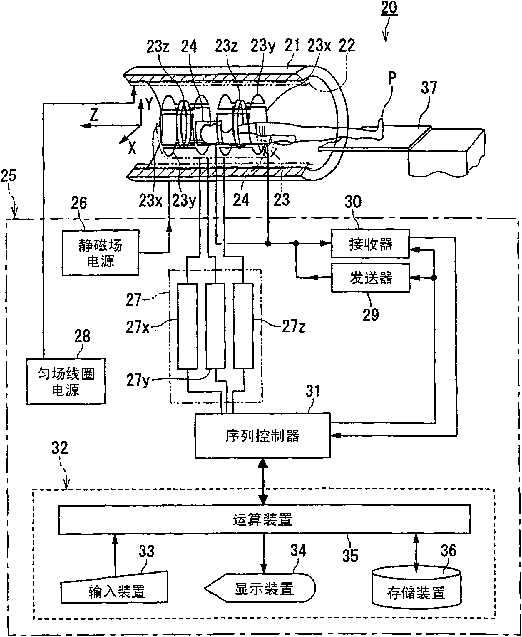
[0025] figure 1 It is a configuration diagram showing an embodiment of the magnetic resonance imaging apparatus according to the present invention.

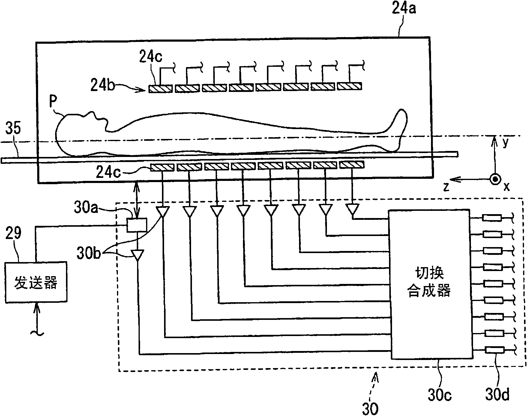
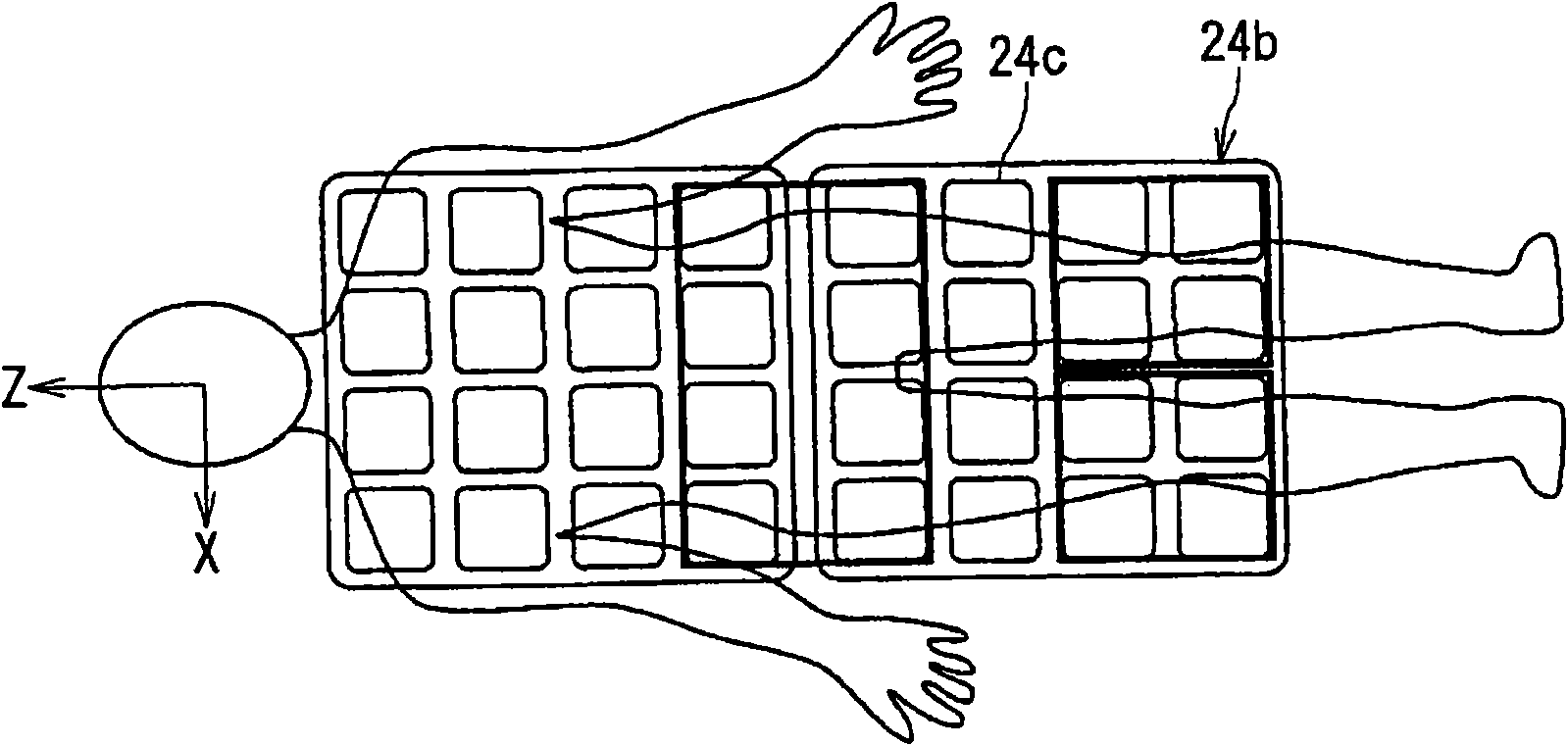
[0026] The magnetic resonance imaging apparatus 20 includes: a cylindrical static magnetic field magnet 21 forming a static magnetic field; a shim coil 22 provided inside the static magnetic field magnet 21 ; a gradient magnetic field coil 23 ; and an RF coil 24 .

[0027] In addition, the magnetic resonance imaging apparatus 20 includes a control system 25 . The control system 25 includes a static magnetic field power supply 26 , a gradient magnetic field power supply 27 , a shim coil power supply 28 , a transmitter 29 , a receiver 30 , a sequence controller 31 and a computer 32 . The gradient magnetic field power supply 27 of the control...


PUM


Abstract

The invention provides magnetic resonace imaging apparatus and magnetic resonance imaging method. A magnetic resonance imaging apparatus includes a trigger generating unit, a blood flow image generating unit and a control unit. The trigger generating unit acquires blood flow information of an object and generates a trigger based on the blood flow information. The blood flow image generating unit acquires imaging data with using the trigger and generates blood flow image data. The control unit controls so as to repeatedly perform a probe sequence for acquiring the blood flow information and animaging sequence for acquiring the imaging data alternately.

Description

field of invention [0001] The present invention relates to a method of using a high frequency (RF: radio frequency, radio frequency) signal of Larmor frequency to magnetically excite the nuclear spin of the object to be detected, and according to the nuclear magnetic resonance (NMR: nuclear magnetic resonance ) signal to reconstruct the magnetic resonance imaging (MRI: Magnetic Resonance Imaging) device and magnetic resonance imaging method, especially related to the MRA (Magnetic Resonance Angiography: Magnetic Resonance Angiography: Magnetic Resonance Angiography) that can implement blood flow information as a trigger to obtain blood flow images A magnetic resonance imaging device and a magnetic resonance imaging method. Background technique [0002] Magnetic resonance imaging is an imaging method that uses a Larmor frequency RF signal to magnetically excite the nuclear spins of a subject in a static magnetic field, and reconstructs an image from the MR signal that accompa...

Claims


Application Information

Patent Timeline
IPC IPC(8): A61B5/055
Inventor 喜种慎一
Owner TOSHIBA MEDICAL SYST CORP
Why Eureka
Try Eureka