Anti-surge PFC circuit

An anti-surge and circuit technology, applied in the direction of electrical components, high-efficiency power electronic conversion, output power conversion devices, etc., can solve the problem of surge current damage to switching tubes, and achieve the effect of avoiding damage

Active Publication Date: 2010-02-10
VERTIV CORP
View PDF0 Cites 21 Cited by
  • Summary
  • Abstract
  • Description
  • Claims
  • Application Information

AI Technical Summary

Problems solved by technology

[0003] The technical problem to be solved by the present invention is to provide an anti-surge PFC circuit for the defect that the switch tube in the bridgeless PFC circuit of the prior art is easily damaged by the surge current

Method used


Image

  • Anti-surge PFC circuit
  • Anti-surge PFC circuit
  • Anti-surge PFC circuit

Examples


Embodiment Construction

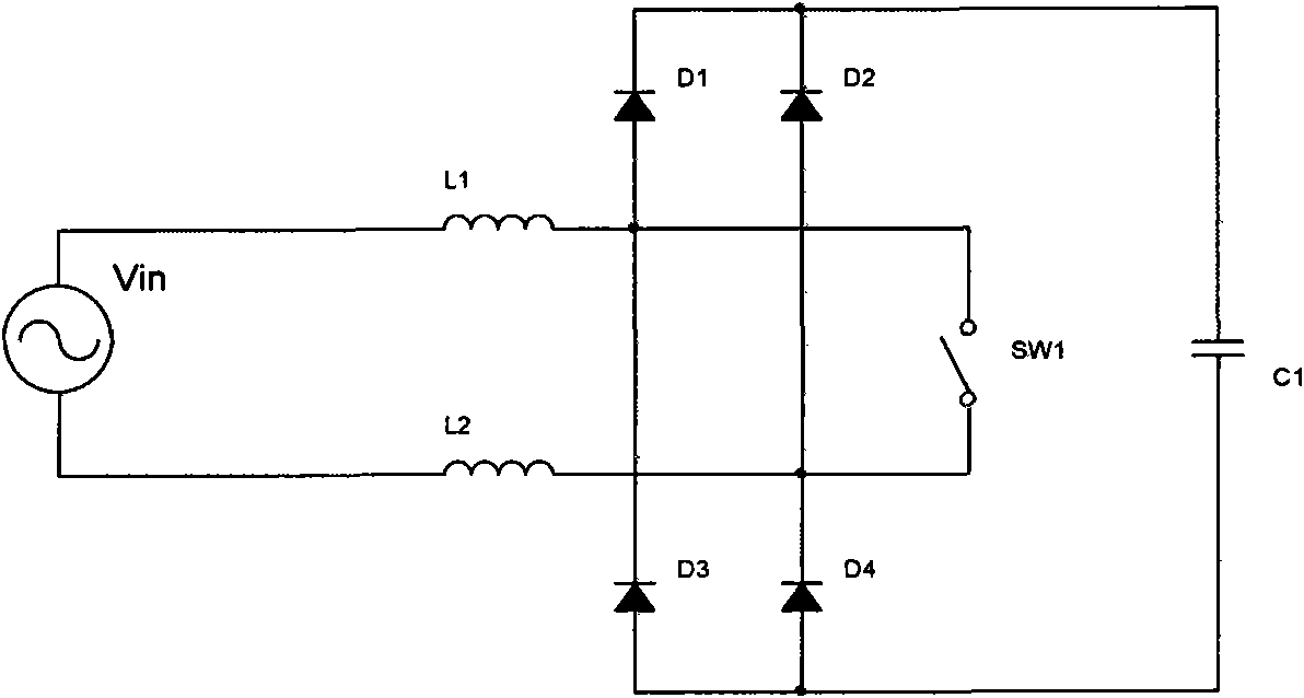
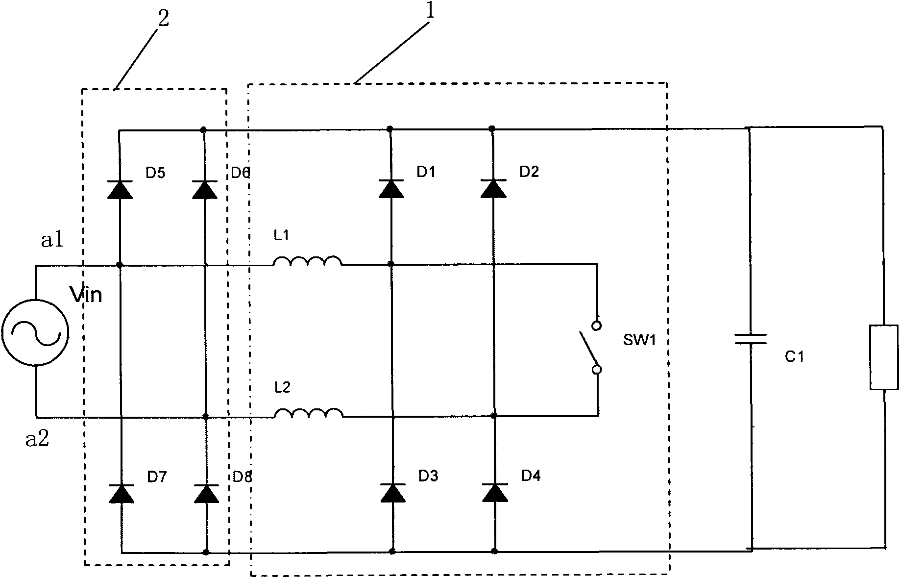
[0036] The PFC power stage circuit of the power supply module typically includes a bridgeless PFC circuit and a filter capacitor connected in sequence between the AC power supply and the load. The main inventive point of the present invention is that the AC power supply and the bridgeless PFC circuit are also connected There is a diode protection circuit, which is used to guide the surge current directly to the filter capacitor C1, that is, add a jumper diode before the bridgeless PFC circuit to achieve the purpose of guiding the surge current and protecting the switching tube in the bridgeless PFC circuit.

[0037] Such as figure 2 As shown, for a specific implementation, the AC power supply is a single-phase two-wire AC; the bridgeless PFC circuit includes: inductors L1, L2, diodes D1, D2, D3, D4, and switch tube SW1; wherein, one end of the inductor L1 is connected to the single-phase The first output end of the two-wire AC is connected, the other end is connected to the a...


PUM


Abstract

The invention relates to an anti-surge PFC circuit, which comprises a bridgeless PFC circuit and a filter capacitor sequentially connected between an alternating current power supply and a load, wherein a diode protective circuit is also connected between the alternating current power supply and the bridgeless PFC circuit and is used for directly guiding surge circuit to the filter capacitor C1. The anti-surge PFC circuit guides the surge current to directly flow to a PFC capacitor by increasing the diode protective circuit which is in bridge connection with an inductor and a diode in the bridgeless PFC circuit so as to prevent the surge current from flowing through the PFC capacitor and prevent the damages to a switching element.

Description

technical field [0001] The present invention relates to a PFC circuit, and more specifically, relates to an anti-surge PFC circuit. Background technique [0002] The technical solution of the existing DC power supply module generally includes an input EMI filter, a PFC power stage, a DC / DC power stage, and the like. The PFC power stage circuit of the power module may adopt a bridgeless PFC circuit: if figure 1 The existing PFC circuit shown uses a bridgeless PFC circuit. For the bridgeless PFC circuit, there is a surge problem: the input surge current will flow through the switch tube sw1, causing damage to the switch tube. Contents of the invention [0003] The technical problem to be solved by the present invention is to provide an anti-surge PFC circuit for the defect that the switch tube in the bridgeless PFC circuit of the prior art is easily damaged by the surge current. [0004] The technical solution adopted by the present invention to solve the technical problem...

Claims


Application Information

Patent Timeline
Patent Type & Authority Applications(China)
IPC IPC(8): H02M1/42H02M1/32
CPCY02B70/126Y02B70/10Y02P80/10
Inventor 张强朱春辉余时强朱岩
Owner VERTIV CORP
Why Eureka
Try Eureka