Safety syringes with retractable needles
A technology for safe syringes and injection needles, applied in the direction of syringes, hypodermic injection devices, infusion sets, etc., can solve the problems of needle rotation, affecting injection effects, and inconvenient assembly, and achieve axial positioning, avoid accidental puncture injuries, and facilitate assembly Effect
- Summary
- Abstract
- Description
- Claims
- Application Information
AI Technical Summary
Problems solved by technology
Method used
Image
Examples
Embodiment 1
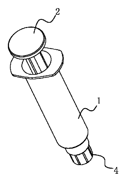
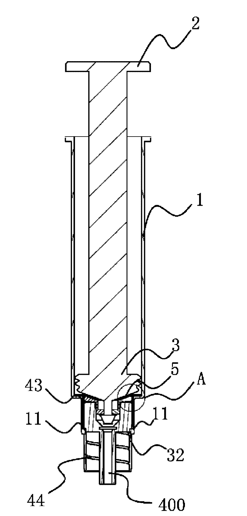
[0029] Such as Figure 1-3 As shown, the safety syringe which can pull back the injection needle includes a syringe 1 and an injection rod 2 arranged in the syringe 1 . A rubber stopper 3 is sheathed on the front end of the injection rod 2 , and a needle seat 4 is installed on the front end of the injection cylinder 1 . A positioning structure capable of preventing the axial forward movement of the needle holder 4 is provided between the syringe 1 and the needle holder 4 . The syringe 1 is provided with a limit ring 5 for preventing the needle seat 4 from moving backward in the axial direction.
[0030] Such as figure 2 , 3, 4 and 6, the center of the needle base 4 has a liquid hole 400. The needle base 4 is composed of a front base body 41 and a rear base body 42. The needle base 4 is provided with a sealing ring 6 capable of forming a seal with the front end of the syringe 1. The sealing ring 6 is arranged on the front base body 41 and the rear base body 42. between. ...
Embodiment 2
[0036] In this embodiment (figure omitted), the front end of the rear seat body 42 has a boss 42a that can be inserted into the rear end of the front seat body 41, and the above-mentioned annular groove 43 is formed between the rear end surface of the rear seat body 42 and the front end surface of the front seat body 41. Here, the rear end surface of the rear seat body 42 and the front end surface of the front seat body 41 are both planes. The rest are similar to those in Example 1, and will not be described in detail herein.
Embodiment 3
[0038] In this embodiment (figure omitted), the rear end of the front seat body 41 has a convex tube that can be inserted into the front end of the rear seat body 42, and the above-mentioned annular groove 43 is formed between the front end surface of the rear seat body 42 and the rear end surface of the front seat body 41. Here, the rear end surface of the rear seat body 42 and the front end surface of the front seat body 41 are both planes. The rest are similar to those in Example 2, and will not be described in detail herein.
PUM
 Abstract
Description
Claims
Application Information
 - R&D
- Intellectual Property
- Life Sciences
- Materials
- Tech Scout
- Unparalleled Data Quality
- Higher Quality Content
- 60% Fewer Hallucinations
Browse by: Latest US Patents, China's latest patents, Technical Efficacy Thesaurus, Application Domain, Technology Topic, Popular Technical Reports.
© 2025 PatSnap. All rights reserved.Legal|Privacy policy|Modern Slavery Act Transparency Statement|Sitemap|About US| Contact US: help@patsnap.com


