Discharge lamp and method for producing a discharge lamp

A technology for discharge lamps and high-pressure discharge lamps is applied in the field of manufacturing such discharge lamps and high-pressure discharge lamps, which can solve the problems of time-consuming and second-best, and achieve the effect of reducing defective products.

Inactive Publication Date: 2010-02-03
OSRAM GMBH
View PDF1 Cites 0 Cited by
  • Summary
  • Abstract
  • Description
  • Claims
  • Application Information

AI Technical Summary

Problems solved by technology

This is also more expensive and leads to only suboptimal results

Method used


Image

  • Discharge lamp and method for producing a discharge lamp
  • Discharge lamp and method for producing a discharge lamp
  • Discharge lamp and method for producing a discharge lamp

Examples


Embodiment Construction

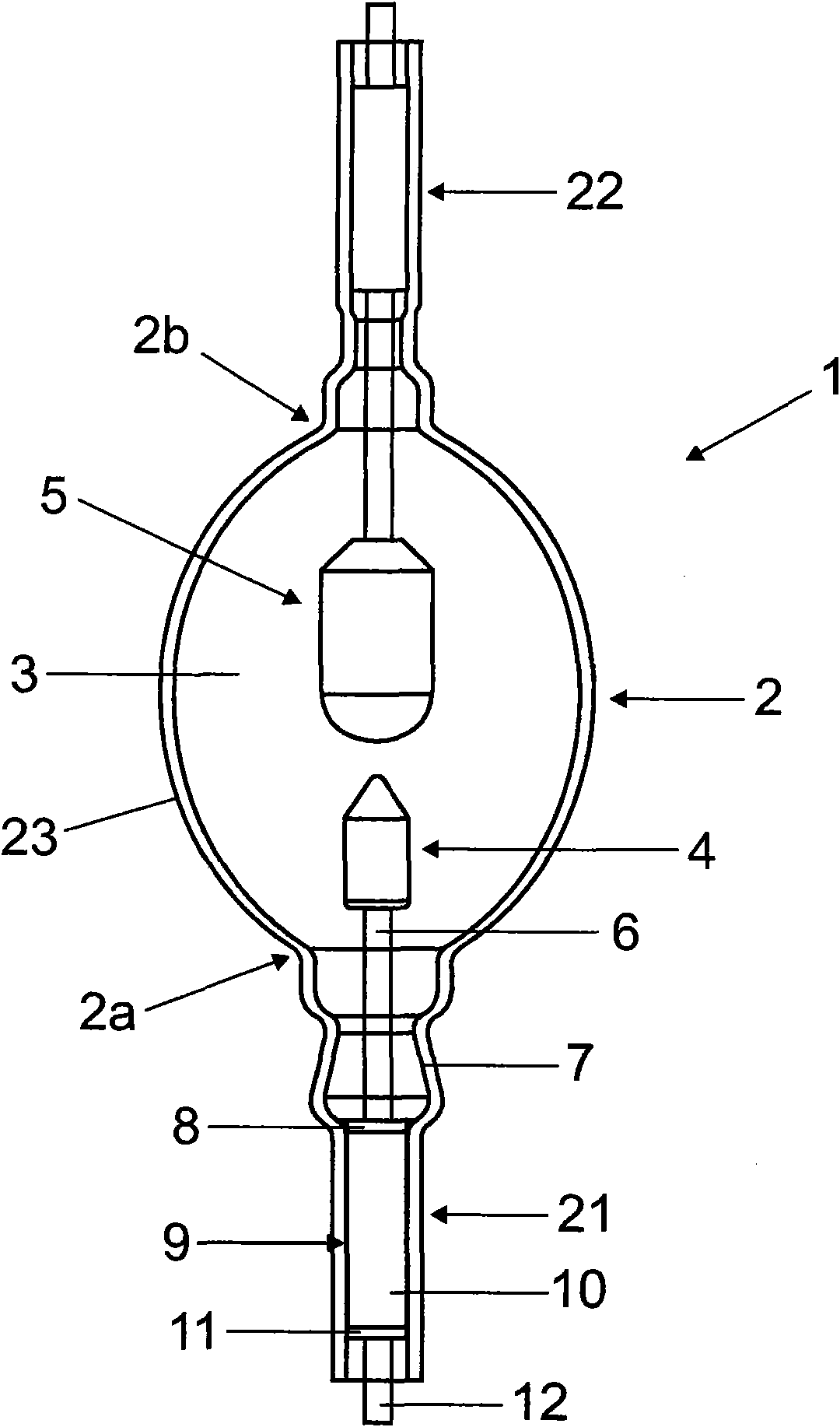
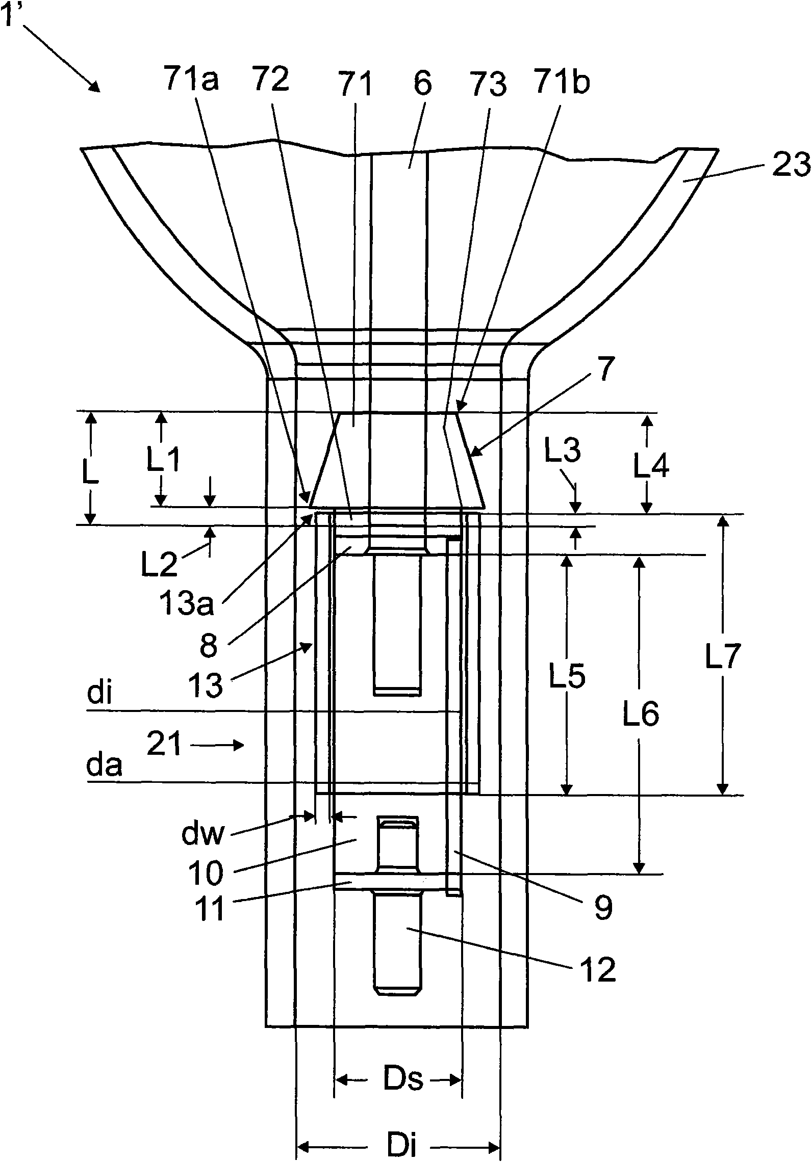
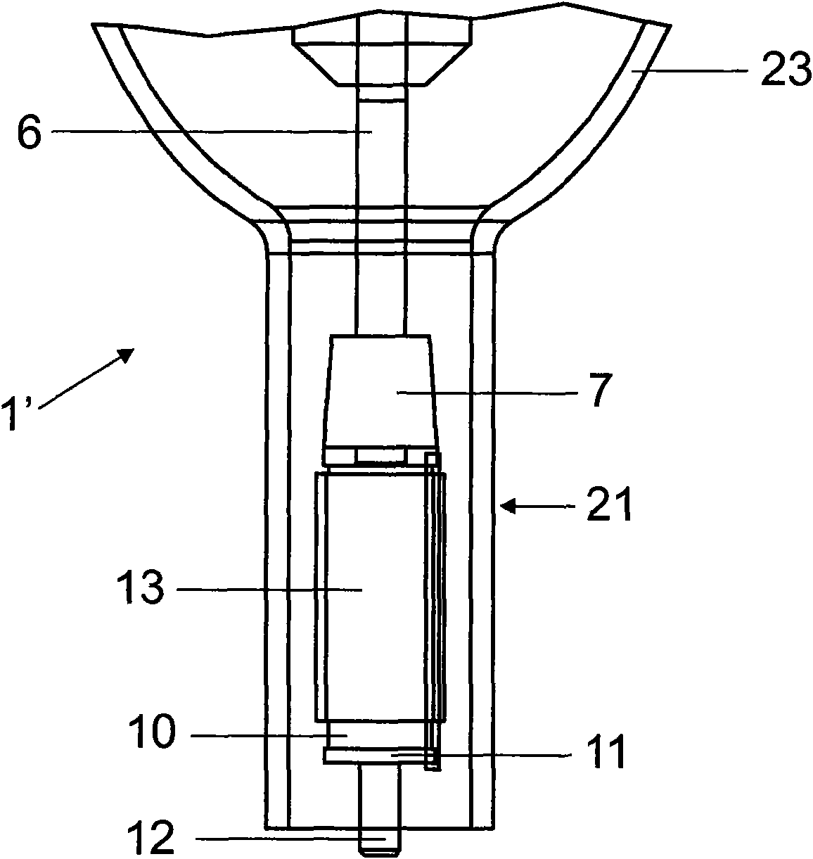
[0039] exist figure 2 A schematic cross-sectional view of a partial region of a discharge lamp 1' constructed as a high-pressure discharge lamp according to the invention is shown in . In principle, this discharge lamp 1' is realized according to the configuration in Fig. 1 . However, the important difference is that the discharge lamp has a base in the region of the bulb neck 21 figure 2 configuration. Similarly, in figure 2 The configuration shown in the region of the bulb neck 21 is also realized in the region of the bulb neck 22 . The configuration on bulb neck 21 is illustrated in detail by way of example.

[0040] In the stem tube of the bulb neck 21 (which transitions into the middle part of the discharge device 2 in the region 2a or in the ellipsoidally shaped partial region 23), a holding rod 6, made of quartz glass as a support, is partially arranged. The supporting part of the small tube 7 , the disc 8 following it and the carrying part following the disc 8 in ...


PUM


Abstract

The invention relates to a discharge lamp, especially a high pressure discharge lamp, comprising a discharge vessel (2), having at least one bulb neck (21, 22) in which a holding rod (6) for an electrode (4, 5), said rod extending into the discharge vessel (3), a carrier element (10) on which at least one current carrying element (9) is arranged, a support element (7) encompassing the holding rod(6), and a tube (13) encompassing the carrier element (10) with the current carrying element (9) are sealed, the tube (13) encompassing the support element (7) across a partial length (L3) that is smaller than the overall length (L) of the support element (7). The invention also relates to a method for producing said discharge lamp.

Description

technical field [0001] The invention relates to a discharge lamp, in particular a high-pressure discharge lamp, with a discharge vessel having at least one bulb neck, a holding rod for an electrode extending into the discharge chamber, on which at least one current-carrying element is arranged The load-carrying part, the support element surrounding the holding rod and the tube surrounding the load-carrying part with the current-carrying element are fused into the bulb neck. Furthermore, the invention relates to a method for producing such a discharge lamp. Background technique [0002] For example, high-pressure discharge lamps, especially mercury vapor lamps (HBO lamps), which are used in the semiconductor industry or in the manufacture of LCD (liquid crystal display) panels, are operated with high operating pressure and high electrical power in order to be able to optimize the emitted The power required for UV (ultraviolet) radiation. [0003] As the electrical power of ...

Claims


Application Information

Patent Timeline
Patent Type & Authority Applications(China)
IPC IPC(8): H01J61/36H01J9/24
CPCH01J9/245H01J61/36H01J61/30
Inventor 赖纳·科格尔卡斯滕·施万特拉尔夫·多特魏希彼得·克雷夫特
Owner OSRAM GMBH
Why Eureka
Try Eureka