
particle counter

A particle counter and light collection technology, which is applied in scientific instruments, individual particle analysis, particle and sedimentation analysis, etc., can solve the problem that the illumination intensity distribution of the detection spot cannot be completely uniform, and the forward scattered light of the detection particle is not detected, which affects the detection accuracy and other problems, to achieve the effect of reducing uneven lighting intensity, compact structure, and reducing maintenance costs

Active Publication Date: 2011-12-14
SANITARY EQUIP INST ACAD OF MILITARY MEDICAL SCI PLA
View PDF2 Cites 0 Cited by
  • Summary
  • Abstract
  • Description
  • Claims
  • Application Information

AI Technical Summary

Problems solved by technology

This method of sampling is simple in structure and easy to implement, but it has obvious defects
It is mainly manifested in two aspects: one is that the particles are easy to accumulate, and the direct-injection sampling structure cannot solve this problem; Dust particles with different particle sizes may get the same scattered light intensity signal when they pass through different positions of the detection spot, which affects the accuracy of detection
In addition, the counters mentioned in the above-mentioned patents have a single detection optical path, and all of them use the side scattered light of the detection particles, but do not detect the relatively strong forward scattered light of the particles.

Method used


Image

  • particle counter
  • particle counter
  • particle counter

Examples


Embodiment Construction

[0023] In order to further understand the invention content, characteristics and effects of the present invention, the following examples are given, and detailed descriptions are as follows in conjunction with the accompanying drawings:

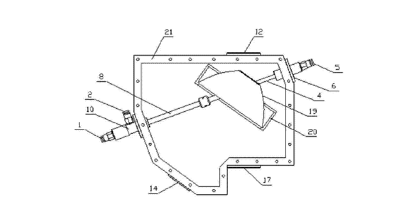
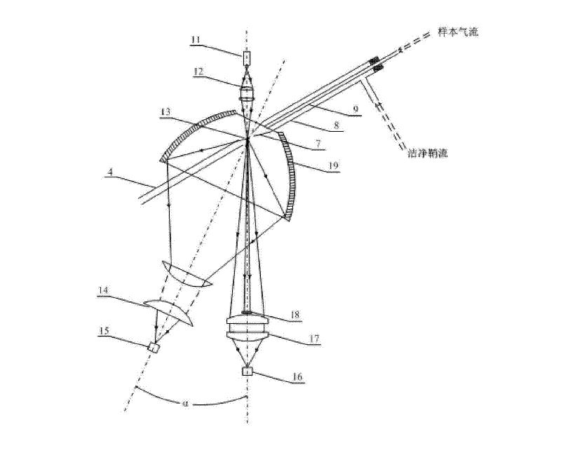
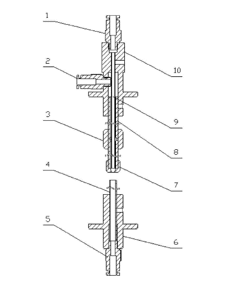
[0024] see Figure 1 ~ Figure 3 , a particle counter of the present invention includes an airtight detection chamber 21, a gas path part and an optical path part.

[0025] See figure 1 and image 3 , the gas path part of a particle counter in the present invention includes a sample tube 9 at the sample injection end, and a sheath flow tube 8 coaxial with the sample tube 9 is set on the outside of the sample tube 9, and the sheath flow tube 8 and the sample gas tube 9 are formed The annular space for clean sheath flow gas to pass through. The concentric adjustment frame 3 is set on the outer wall of the sheath flow tube 8. At least three adjustment screws are evenly distributed along the circumference of the adjustment frame 3. The adjustmen...


PUM


Abstract

The invention discloses a particle counter, which comprises an airtight detection chamber, a gas path and an optical path; the gas path includes a coaxially arranged sampling gas pipe and a receiving pipe fixedly connected with the airtight detection chamber; The light source of the light beam is provided with an incident lens group affixed to the airtight detection chamber and a curved mirror with an opening fixed to the airtight detection chamber in the forward direction of the light beam emitted by the light source. The focal point is located at the intersection of the optical path and the gas path, and the curved mirror is provided with a side light collection and detection device; the outer surface of the sample gas pipe is provided with a coaxial sheath flow tube, and the sheath flow tube and the An annular space for clean sheath flow gas to pass is formed between the sample gas tubes, the gas outlet end of the annular space is flush with the gas outlet end of the sample tube, and a nozzle is connected to the gas outlet end of the sheath flow tube. The invention can effectively prevent the diffusion of the sample gas flow, thereby improving the detection accuracy.

Description

technical field [0001] The invention relates to air cleanliness testing equipment, in particular to a particle counter. Background technique [0002] Many industries, such as medicine, electronics, precision machinery, color tube manufacturing, microorganisms, etc., have high requirements for the cleanliness of the air in the workshop. The cleanliness level of the clean workshop is often determined by the maximum number of particles allowed in the air per unit volume. That is, the particle count concentration is measured. The old US Federal Standard 209E "Cleanliness Levels of Airborne Particles in Clean Rooms and Clean Areas" has been replaced by the new International Standard IS014644-1 "Clean Rooms and Related Controlled Environments, Part 1: Air Cleanliness" on November 29, 2001. Degree classes" and IS014644-2 "Cleanrooms and related controlled environments, Part II: Technical conditions for testing and monitoring for certification of conformity to IS014644-1". In orde...

Claims


Application Information

Patent Timeline
Patent Type & Authority Patents(China)
IPC IPC(8): G01N15/10
Inventor 詹宁波吴太虎杜耀华陈锋朱友平程智赵丕成
Owner SANITARY EQUIP INST ACAD OF MILITARY MEDICAL SCI PLA
Learn More