
Upper and lower combined scraping plate transmission mechanism for track type ballast scarifiers

A conveying mechanism and crawler-type technology, which is applied in the field of crawler-type mucking machine conveying mechanism, can solve the problems of easily damaged conveying mechanism, falling in the roadway, safety accidents, etc., and achieves compact structure, high conveying efficiency and strong applicability Effect

Inactive Publication Date: 2011-05-18
李凯
View PDF0 Cites 4 Cited by
  • Summary
  • Abstract
  • Description
  • Claims
  • Application Information

AI Technical Summary

Problems solved by technology

[0002] The conveying mechanism of the crawler-type mucking machine is driven by a scraper chain. The traditional conveyor chain scraper is a rod-plate structure. When conveying pulpy materials, especially in inclined roadways, it is often difficult to There is a certain distance between the plates, and the scraper of the rod-plate structure has poor ability to accumulate pulpy materials, resulting in poor conveying effect of the scraper, which cannot meet the actual needs of the project; moreover, due to the low position of the scraper on the traditional conveying mechanism, Generally, it is only suitable for conveying stones in flat roadways or roadways with small inclination angles. When conveying long and round large stones in large inclined roadways, the position of the scraper is low, and the large scraper on the upper part of the transport trough scraper machine Rocks are easy to roll over on the conveyor belt. Rolling large stones are not only easy to damage the conveying mechanism, but also fall into the roadway, which greatly reduces the efficiency of scraper conveying, and may even cause safety accidents

Method used


Image

  • Upper and lower combined scraping plate transmission mechanism for track type ballast scarifiers
  • Upper and lower combined scraping plate transmission mechanism for track type ballast scarifiers
  • Upper and lower combined scraping plate transmission mechanism for track type ballast scarifiers

Examples


Embodiment Construction

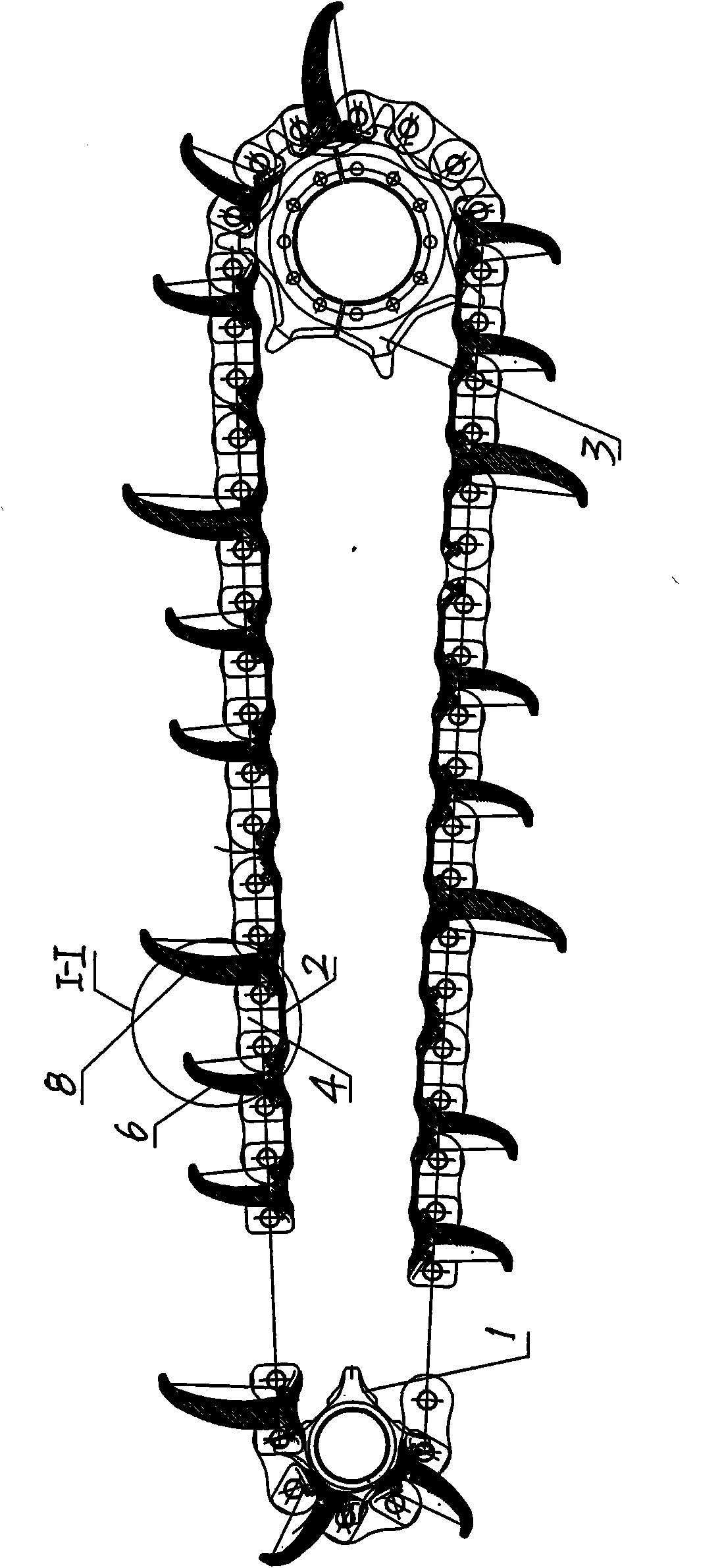
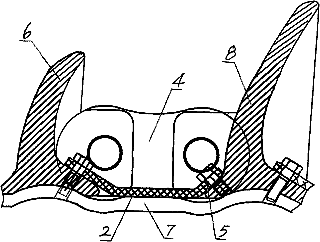
[0013] exist figure 1 and figure 2 Among them, the high and low combination scraper conveying mechanism of the crawler-type mucking machine includes two driving sprockets 3 and two driven sprockets 1 mounted on the transmission shaft, and each pair of driving sprockets and driven sprockets is provided with The roller chain is provided with an inner chain plate 7 between the two roller chains. The roller chain is formed by connecting several rollers 4 to each other. The inner chain plate is fixedly connected with a scraper I 6 and Scraper II 8, at figure 1 and figure 2 In the shown embodiment, the scraper I and the scraper II are both arc-shaped in cross-section, and the arrangement of the scraper I and the scraper II on the inner chain plate is as follows: every two rollers form a group, There are two rollers between the groups to form an interval distribution. A scraper I 6 is arranged on the inner chain plate between the rollers of the group and the position of the two ...


PUM


Abstract

The invention discloses an upper and lower combined scraping plate transmission mechanism for track type ballast scarifiers, comprising driving chain wheels (3) and driven chain wheels (1) installed on both ends of a transmission shaft. Each pair of driving chain wheels and driven chain wheels is provided with roller chains; an inner chain plate (7) is arranged between the two roller chains; the roller chains are formed by mutually connecting rollers (4); the inner chain plate is provided with a scraping plate I (6) and a scraping plate II (8); rubber plates (2) are arranged among the scraping plate I, the scraping plate II and the inner chain plate; the cross sections of the scraping plate I and the scraping plate II are arc hopper-shaped cross sections; and the scraping plate II (8) is higher than the scraping plate I (6). In the invention, the scraping plates are changed into arc hopper-shaped cross sections and are designed into shapes with different heights. Thereby, pasty materials accumulated on the bottom of the scraping plates can be transmitted to the upper part, achieving the purpose of transmitting the pasty materials. Moreover, stone blocks, especially large stone blocks, can be transmitted efficiently and safely in large-angle oblique mine tunnels. The upper and lower combined scraping plate transmission mechanism has the advantages of compact structure, strong applicability and high transmission efficiency and is widely suitable for transmitting the pasty materials and the large stone blocks in the oblique mine tunnels.

Description

technical field [0001] The invention relates to a conveying mechanism of a crawler-type dregs remover, in particular to a conveying mechanism of a crawler-type dregs-removed machine used for conveying materials in inclined tunnels of mines. Background technique [0002] The conveying mechanism of the crawler-type mucking machine is driven by a scraper chain. The traditional conveyor chain scraper is a rod-plate structure. When conveying pulpy materials, especially in inclined roadways, it is often difficult to There is a certain distance between the plates, and the scraper of the rod-plate structure has poor ability to accumulate pulpy materials, resulting in poor conveying effect of the scraper, which cannot meet the actual needs of the project; moreover, due to the low position of the scraper on the traditional conveying mechanism, Generally, it is only suitable for conveying stones in flat roadways or roadways with small inclination angles. When conveying long and round l...

Claims


Application Information

Patent Timeline
Patent Type & Authority Patents(China)
IPC IPC(8): B65G19/00B65G19/20B65G19/24E21F13/00
Inventor 李凯唐福新
Owner 李凯
Learn More