
Method for conveying objects

A technology of object movement, applied in the field of transportation of particularly light objects, which can solve problems such as wear and tear, and achieve the effects of energy saving, highly dynamic energy, and fast conversion time

Inactive Publication Date: 2010-01-27
诺豪工程股份公司
View PDF0 Cites 20 Cited by
  • Summary
  • Abstract
  • Description
  • Claims
  • Application Information

AI Technical Summary

Problems solved by technology

Here, enormous forces act on the system and, moreover, this is subject to a great deal of wear

Method used


Image

  • Method for conveying objects
  • Method for conveying objects
  • Method for conveying objects

Examples


Embodiment Construction

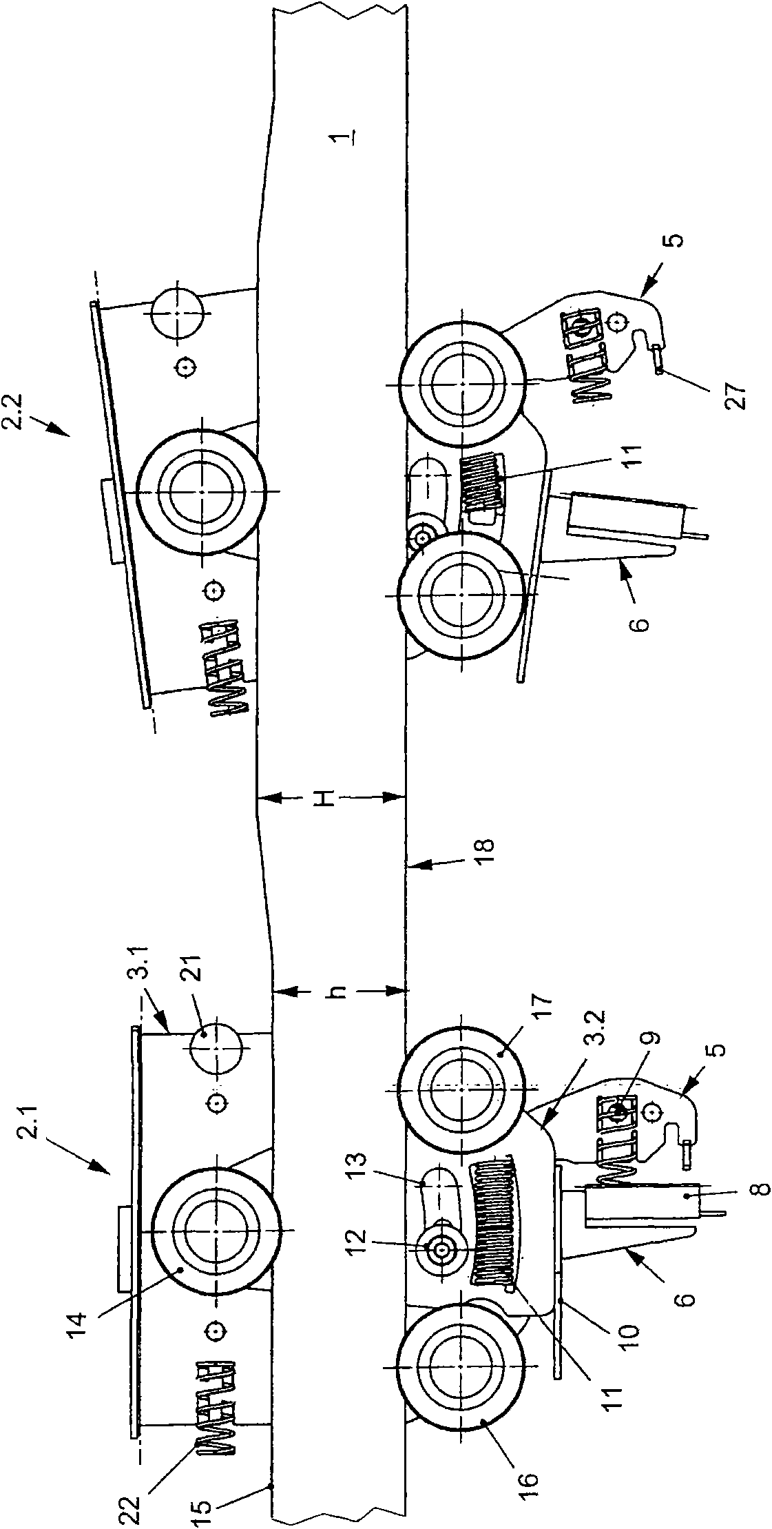
[0103] exist figure 1 shows a guide rail 1 along which two clamping vehicles 2.1 and 2.2 travel. Since the two clamping vehicles 2.1 and 2.2 are designed identically, only one of them will be described below.

[0104] Each clamping vehicle 2 . 1 , 2 . 2 has two clamping arms 3 . 1 and 3 . During rotation around the axis of rotation 4 , the clamping arms 3 . 1 and 3 . 2 open in a scissors-like fashion, wherein the outer jaw 5 is separated from the inner jaw 6 , as seen in the clamping vehicle 2 . 2 .

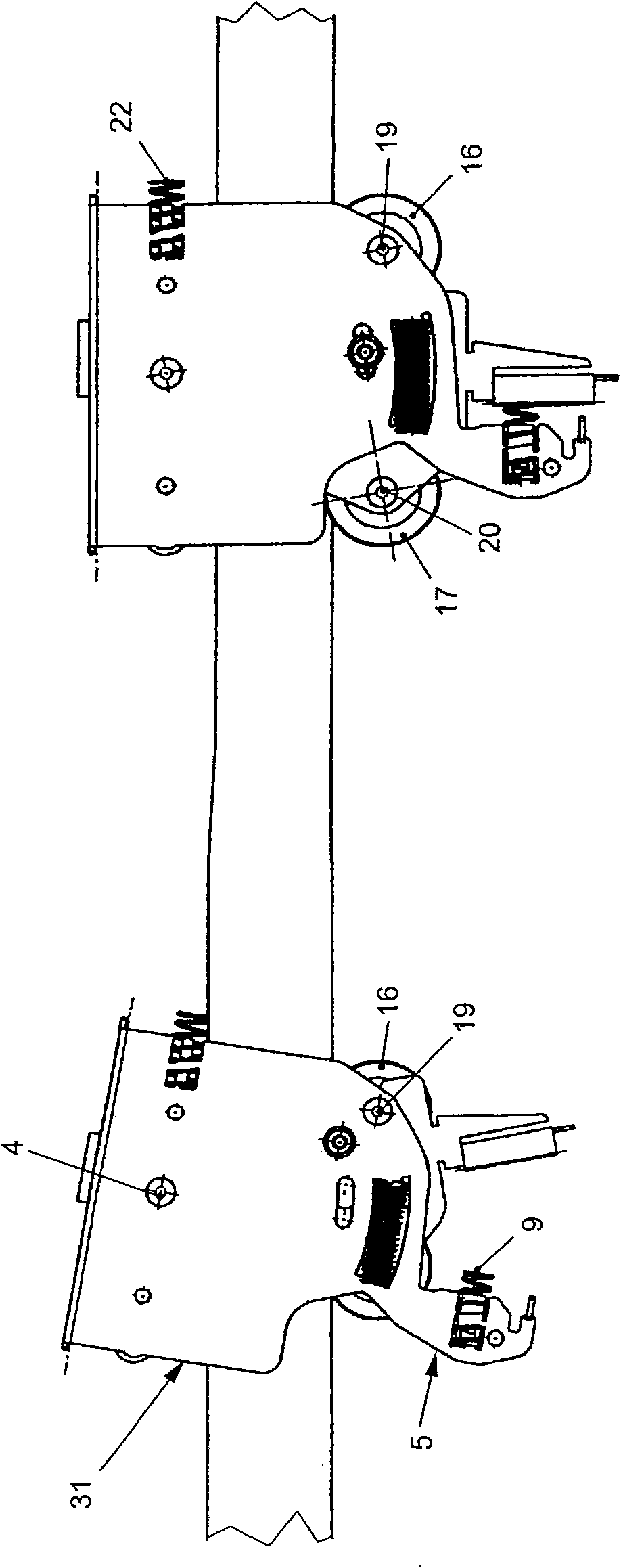
[0105] The outer jaw 5 is preferably connected integrally with the rear wall 7 to the clamping arm 3.1, wherein it is also called the base leg, since it is mainly formed from flat steel, as first described in figure 2 as seen in .

[0106] The inner jaw 6 is also formed at least partially in one piece with the clamping arm 3 . 2 , wherein both are also mainly formed from flat steel, so that the clamping arm is also called a shear leg. A pressure element 8 is arranged on the ...


PUM


Abstract

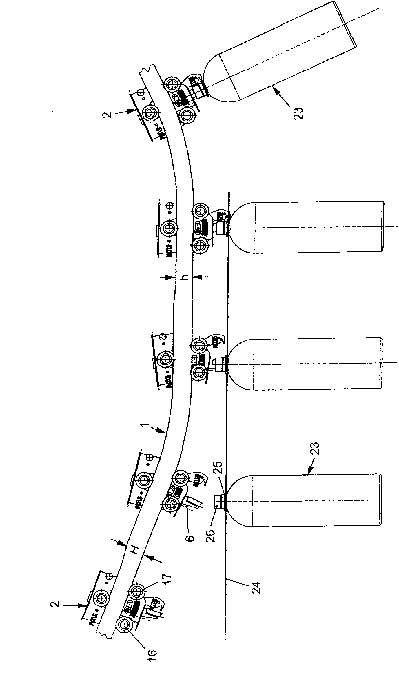
Disclosed is a method for conveying especially light objects (23, 23.1), particularly empty or full PET bottles. In said method, the object (23, 23.1) is accepted between two claws (5, 6) of claw arms (3.1, 3.2) of a gripping vehicle (2, 2.1, 2.2, 2.3, 2.4) which moves along a rail (1, 1.1, 1.2).

Description

technical field [0001] The invention relates to a method for transporting particularly light objects, in particular empty PET bottles or filled PET bottles, and a device for the method. Background technique [0002] In many industries there is a need to transport objects from a handling station to the nearest handling station or packing station or the like. The present invention relates to all objects, in particular to those objects having a hole or a type similar to a hole and objects having a neck ring or a structure similar to a neck ring. First of all, they concern PET-containers. The PET industry is a highly technical field of work in the packaging industry and has grown enormously because the advantages of PET containers are obvious. PET bottles of all possible shapes, sizes and colors can be formed in an expensive step. For this purpose, preforms are generally produced first and then, if necessary, transported to rolling blowers by cold and / or hot rolling. The pre...

Claims


Application Information

Patent Timeline
IPC IPC(8): B65G9/00
CPCB65G9/002B65G2201/0247B65G9/008B65G9/004
Inventor 弗朗兹·克莱博彼得·诺瓦克
Owner 诺豪工程股份公司
Learn More