
Pressure sensor

A pressure sensor and pressure unit technology, used in the measurement of fluid pressure, instruments, and fluid pressure measurement through electromagnetic components, which can solve problems such as pressure measurement value errors

Inactive Publication Date: 2010-01-27
SEIKO EPSON CORP
View PDF2 Cites 20 Cited by
  • Summary
  • Abstract
  • Description
  • Claims
  • Application Information

AI Technical Summary

Problems solved by technology

Therefore, although the pressure sensor 300 is intended only for the pressure of gas or liquid, an error occurs in the pressure measurement value due to the installation posture.

Method used


Image

  • Pressure sensor
  • Pressure sensor
  • Pressure sensor

Examples


Embodiment Construction

[0054] Next, the pressure sensor of the present invention will be described in detail using the illustrated embodiments. However, unless otherwise specified, the constituent elements, types, combinations, shapes, and relative arrangements described in the embodiments are not intended to limit the scope of the present invention thereto, but are merely illustrative examples.

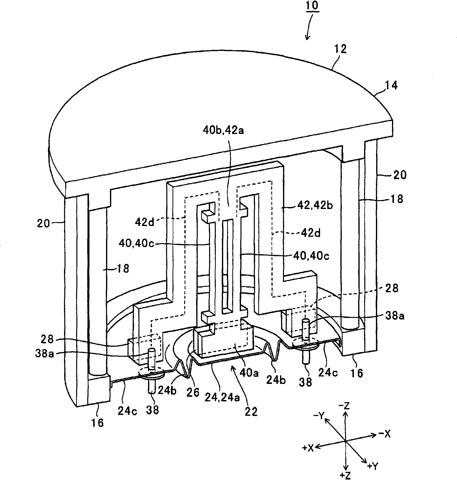
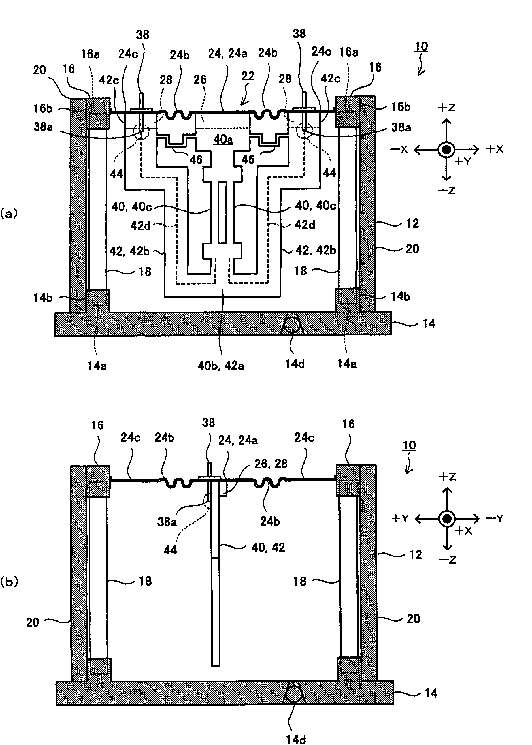
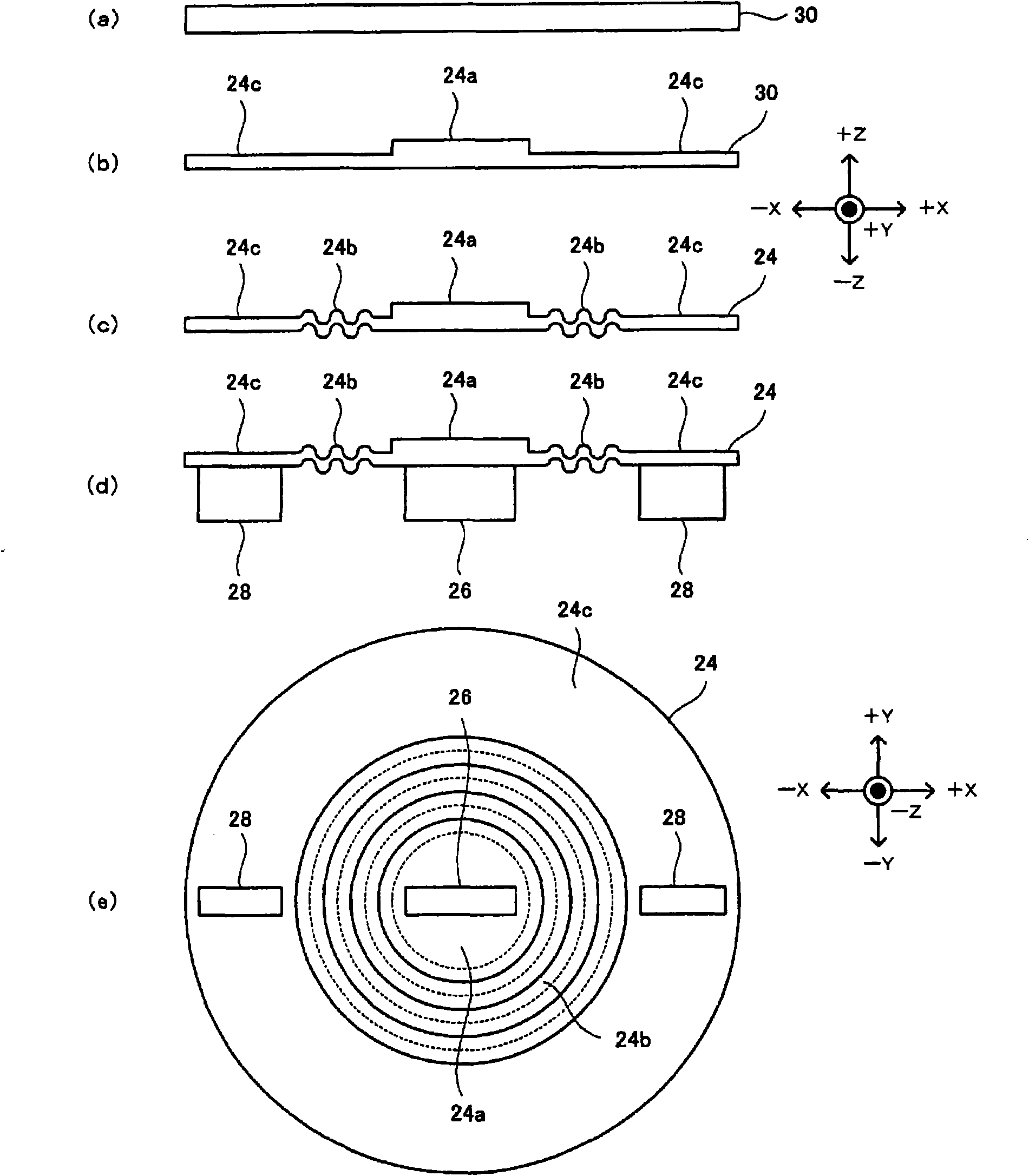
[0055] figure 1 (taking the XZ plane as a cross section) is a perspective view showing the pressure sensor of the first embodiment, figure 2 ( figure 2 (a) Taking the XZ plane as a section, figure 2 (b) YZ plane is a sectional view) shows a sectional view. in addition, figure 1 , 2 The shown ZYX forms a rectangular coordinate system, and the same applies to the drawings used hereinafter. The pressure sensor 10 of the first embodiment has a housing 12, a diaphragm 24 as a pressure receiving unit, a pressure sensitive element 40, a connecting member 42 as a connecting unit, and a reinforcing part ...


PUM


Abstract

The invention provides a pressor sensor for reducing error of pressure measurements. The pressure sensor includes: a housing; a pressure receiver which seals an opening of the housing and transmits pressure from outside the housing to the inside of the housing; and a pressure sensing element having a pressure sensing portion and a pair of base portions which are respectively coupled to both ends of the pressure sensing portion. In the pressure sensor, a force detecting direction is set to be a detection axis, a line connecting the pair of base portions and a displacement direction of the pressure receiver are arranged in parallel, one of the base portions is coupled to a central region, which is displaced by the pressure, of the pressure receiver, and the other of the base portions is coupled to a marginal region, which is at a fixing side, of the pressure receiver through a connecting member.

Description

technical field [0001] The present invention relates to a pressure sensor using a pressure sensitive element and a diaphragm, and particularly relates to a technology for reducing errors in temperature changes in pressure measurement values ​​of the pressure sensor due to combinations of different types of materials, and errors due to gravity of the diaphragm. Errors in measured pressure values ​​due to deflection. Background technique [0002] Conventionally, pressure sensors using piezoelectric vibrating elements as pressure sensitive elements, such as water pressure gauges, barometers, and differential pressure gauges, are known. In the piezoelectric vibrating element, for example, an electrode pattern is formed on a plate-shaped piezoelectric substrate, a detection axis is set in a force detection direction, and when pressure is applied in the direction of the detection axis, the resonance frequency of the piezoelectric vibrator changes, pressure is detected based on ch...

Claims


Application Information

Patent Timeline
IPC IPC(8): G01L9/08G01L27/00
CPCG01L9/0022G01L19/02G01L9/08G01L7/08
Inventor 渡边润藤崎昌伸本山久雄
Owner SEIKO EPSON CORP
Learn More