Heat accumulating device

A heat storage device and heat storage technology, applied in the direction of heat storage equipment, indirect heat exchangers, heat exchanger types, etc., can solve the problems of inversion and heat storage obstacles, and achieve the effect of increasing heat energy and improving utilization efficiency

Inactive Publication Date: 2010-01-13
TOYOTA JIDOSHA KK +1
View PDF1 Cites 0 Cited by
  • Summary
  • Abstract
  • Description
  • Claims
  • Application Information

AI Technical Summary

Problems solved by technology

Therefore, when a plurality of heat source fluids having different temperatures are circulated through the flow paths to store heat in the heat storage material, the temperature of the heat storage material rises, and the temperature of the heat storage material and the area around the portion where the low-temperature heat source fluid flows will decrease. The difference in temperature of the low-temperature heat source fluid disappears, or sometimes reverses, and heat storage from the low-temperature heat source fluid toward the heat storage material is hindered

Method used


Image

  • Heat accumulating device
  • Heat accumulating device
  • Heat accumulating device

Examples


Embodiment Construction

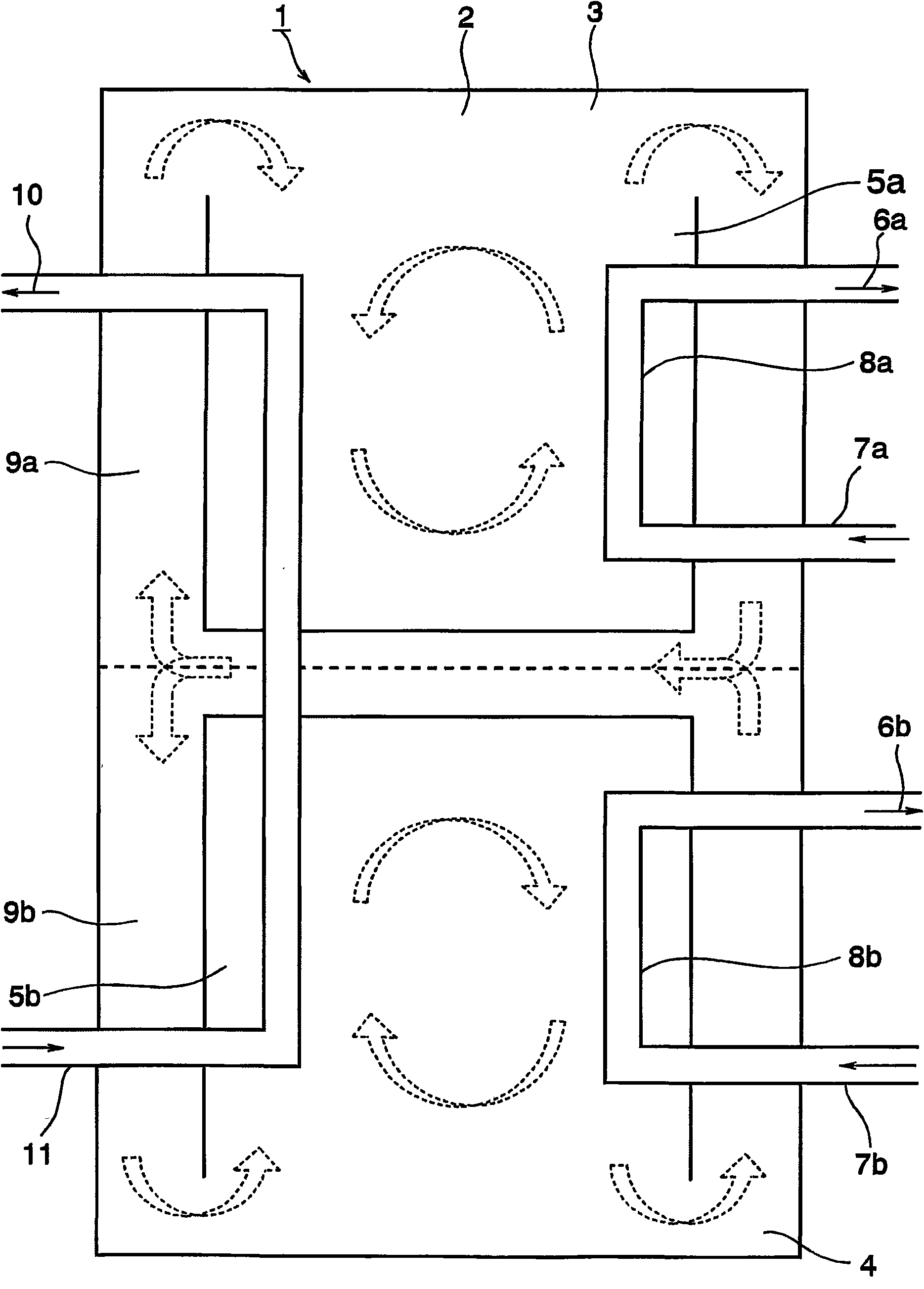
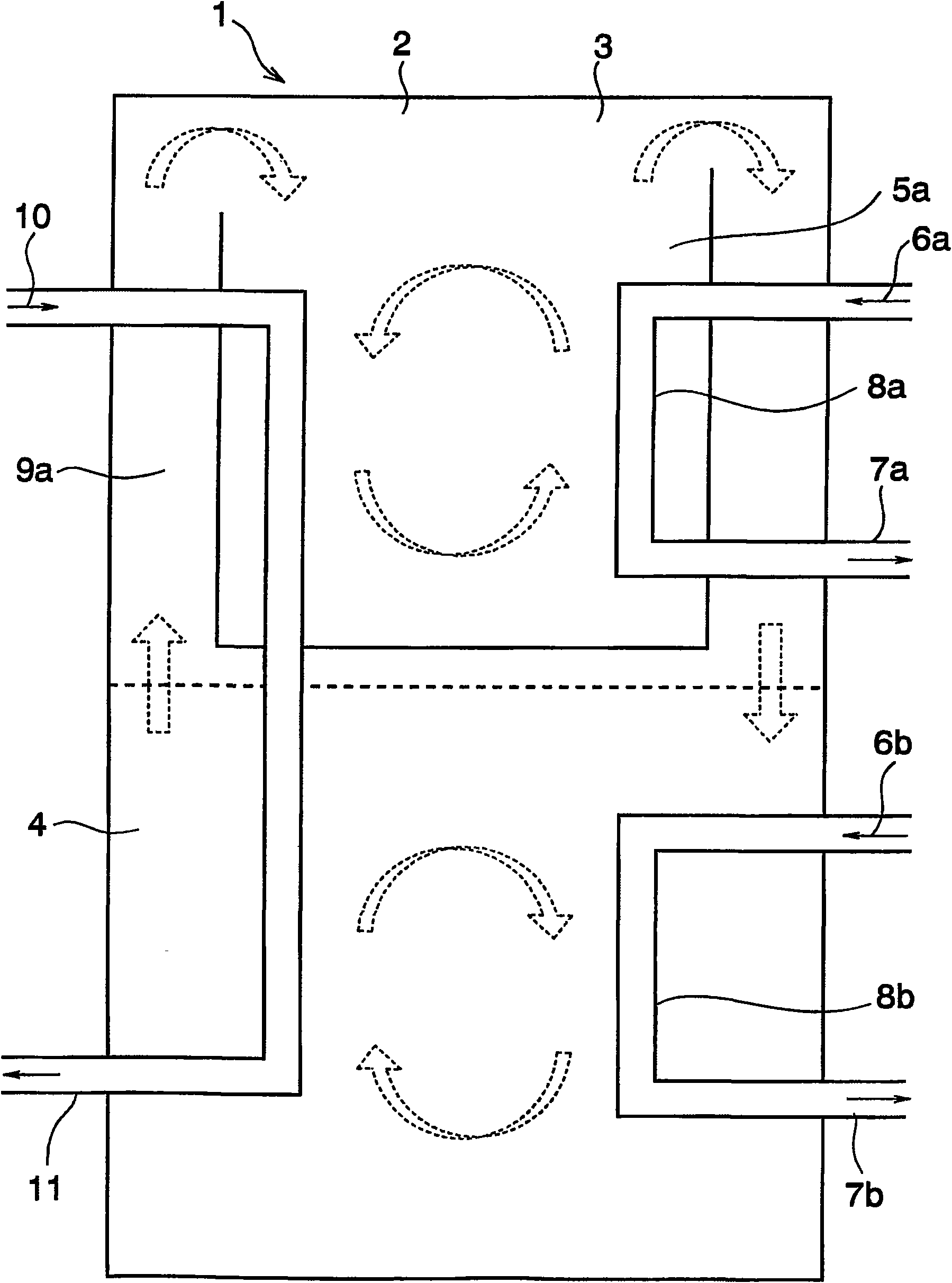
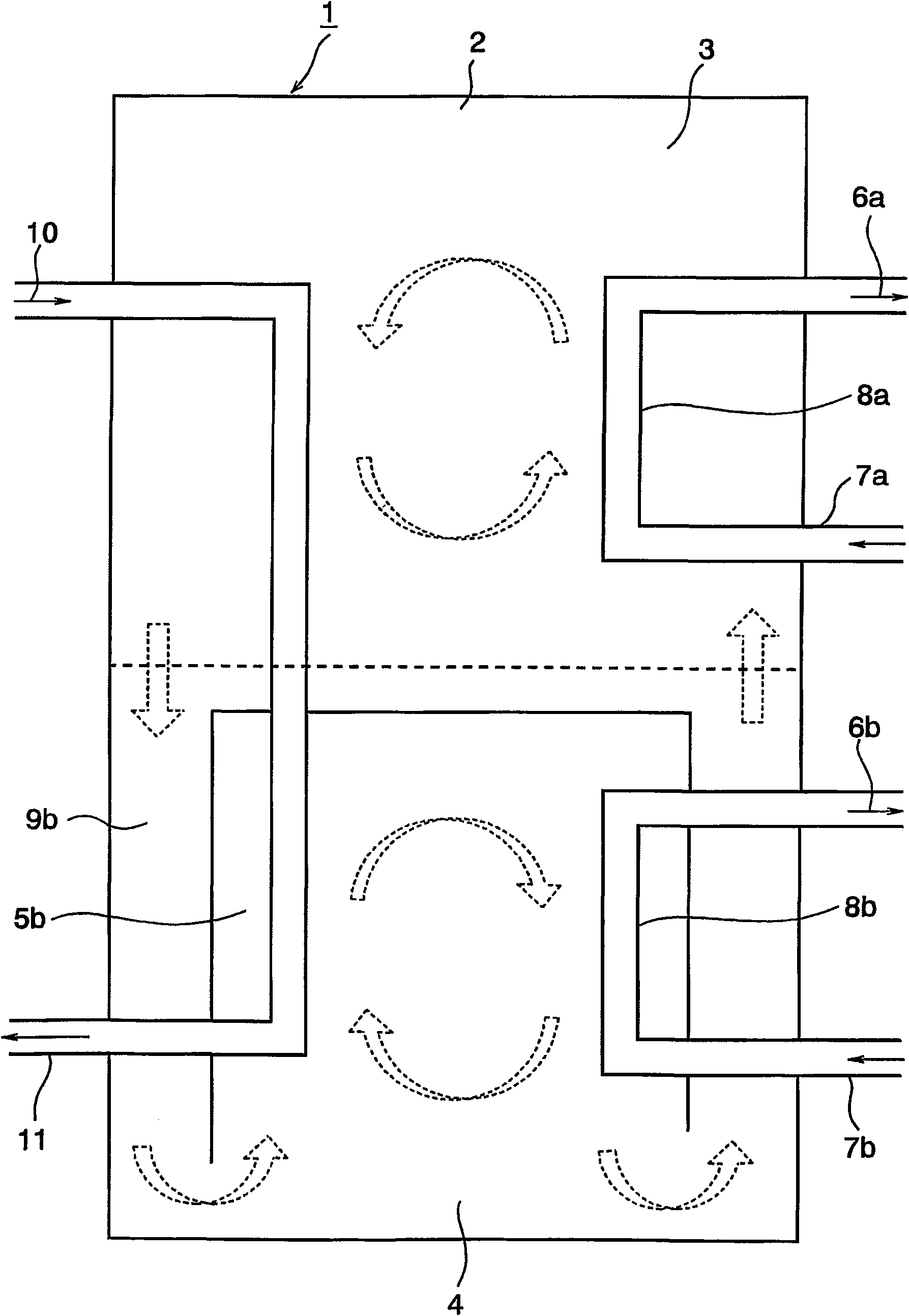
[0022] Next, the present invention will be described more specifically. figure 1 An example of the present invention is schematically shown, and it is a diagram showing convection of the heat storage material in the heat storage device according to the present invention. A fluid heat storage material 2 is accommodated in the heat accumulator 1 , and the heat accumulator 1 is divided vertically, and the upper side is the first heat storage tank 3 and the lower side is the second heat storage tank 4 . The first heat storage tank 3 and the second heat storage tank 4 are joined so that the heat storage material 2 can flow between the heat storage tanks.

[0023] An inner tank 5a is provided inside the first heat storage tank 3, and the inner tank 5a is closed on the dividing side and the side side of the first heat storage tank 3 and the second heat storage tank 4, and is closed on the side opposite to the dividing side. One side is open. And, inside the inner tank 5a, a heat-in...


PUM


Abstract

Intended is to cause a heat accumulating device using a natural convection according to a temperature difference in the temperature distribution of a heat accumulating material, to accumulate heat by means of a plurality of heat transfer media. The heat accumulating device comprises a plurality of heat transfer media (6a and 6b) of different temperatures, a heat accumulating member (2) for receiving heats from the individual heat transfer media (6a and 6b) to accumulate or regenerate the heats, a heat accumulator (1) housing the heat accumulating member (2), and a first heat accumulating bath(3) and a second heat accumulating bath (4) formed by partitioning the heat accumulator (1). The heat accumulating device can perform the heat exchange between the heat transfer media (6a and 6b) andthe heat accumulating member (2) in the individual heat accumulating baths (3 and 4). The heat accumulating device is characterized in that at least one of the first heat accumulating bath (3) and the second heat accumulating bath (4) is provided therein with inner baths (5a and 5b), which are closed on the side of the boundary portion from the other heat accumulating bath and opened on the otherside, and in that heat exchanging portions (8a and 8b) for performing heat exchanges between the heat transfer media (6a and 6b) and the heat accumulating member (2) are formed in the inner sides of the inner baths (5a and 5b).

Description

technical field [0001] The present invention relates to a heat storage device in which a plurality of heat input media circulate through a heat storage material, and relates to a heat storage device capable of storing warm or cold heat. Background technique [0002] Conventionally, in heat exchangers, heat accumulators, and cold accumulators, as a structure for exchanging heat between heat input media, it is known that a heat source fluid and a heat recovery fluid flow separately inside the heat storage material. The structure of the integrated porous casing. One example thereof is described in JP-A-2003-336974. In the invention described in Japanese Patent Application Laid-Open No. 2003-336974, a plurality of the above-mentioned porous sleeves are arranged at regular intervals inside the heat storage material, and the porous sleeves are arranged in the first container through which the heat source fluid and the heat recovery fluid flow. and in the second container. [00...

Claims


Application Information

Patent Timeline
Patent Type & Authority Applications(China)
IPC IPC(8): F28D20/00
CPCF28D20/0039F28D2020/0086F28D2020/0078Y02E60/142F28F2270/00F28D2020/0082Y02E60/14
Inventor 坪根贤二端圣一塚原政仁福泽正隆成田浩司
Owner TOYOTA JIDOSHA KK
Why Eureka
Try Eureka