Equipment for capturing and converting energy
A technology of energy capture and conversion equipment, applied in mechanical equipment, ocean energy power generation, engine components, etc., can solve the problems of complex mechanical structure, inability to obtain energy, and high manufacturing costs, and achieve extended maintenance cycles, less water surface installation work, The effect of improving wind and wave resistance
- Summary
- Abstract
- Description
- Claims
- Application Information
AI Technical Summary
Problems solved by technology
Method used
Image
Examples
Embodiment approach 1
[0025] The energy conversion hammer has no movable parts in the hammer body, and the energy conversion parts or most of the transmission parts are connected between the frame and the hammer body, and are located outside the hammer body. This method has no obvious advantages and is only used in specific situations.
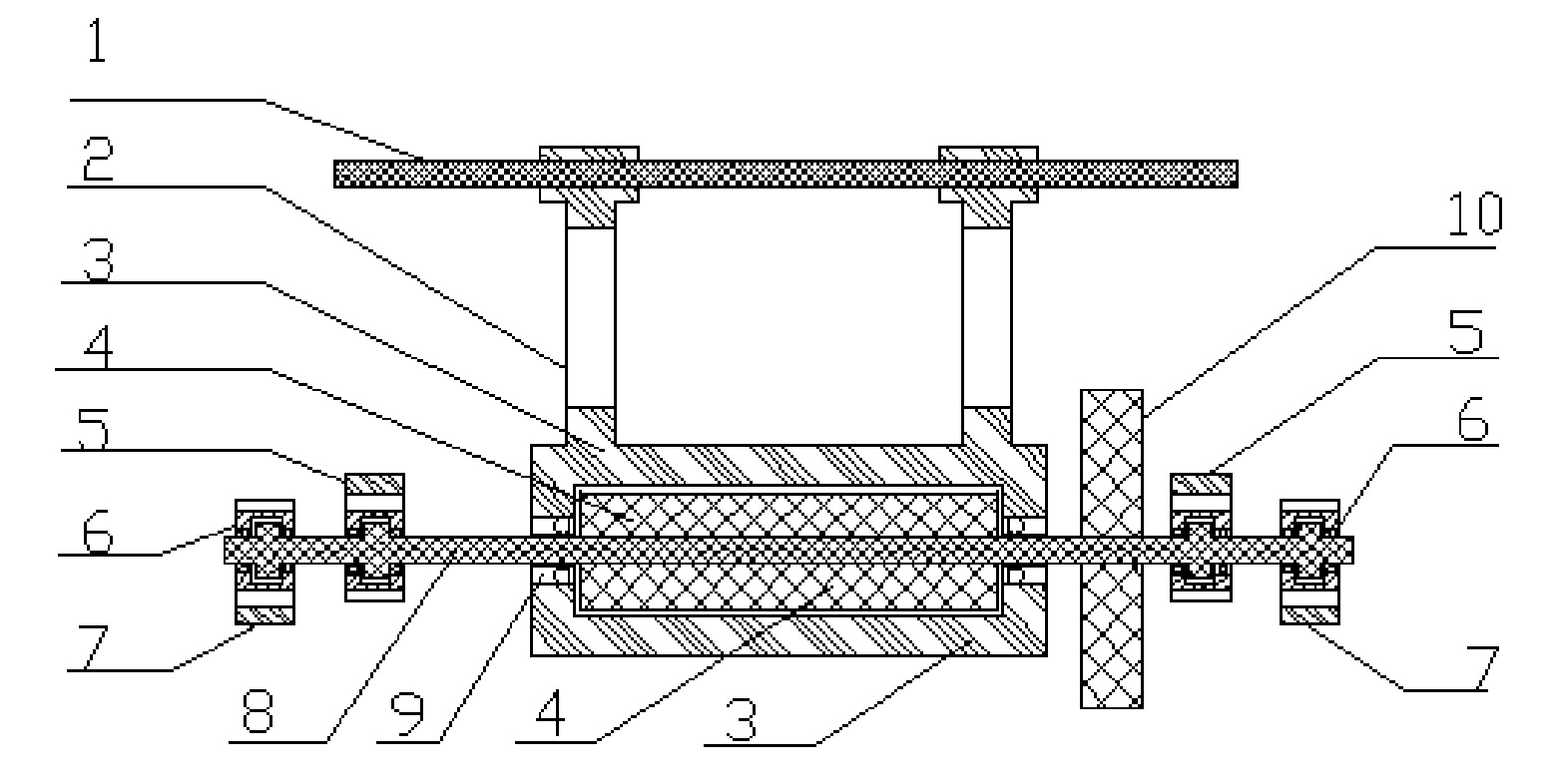
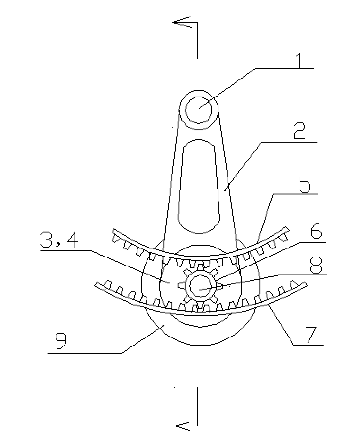
[0026] The frame and hammer body of the wave energy capture and conversion equipment are used as transmission components to directly output mechanical energy or provide mechanical energy to the energy conversion system. In this mode, the equipment has a waterproof casing, and one or more sets of energy-transforming hammer systems are arranged inside, and each set of energy-transforming hammers includes at least one set of hammer bodies. The energy-transforming hammer hangs in the equipment through the hammer rod 2 and the hammer shaft 1, or is supported by the bracket 11 in a contact or non-contact manner. figure 2 , 3 , 4, 5), the area in the horizontal directio...
Embodiment approach 2
[0030] The hammer body of the energy-transforming hammer contains a movable part, the connection between the frame and the movable part of the hammer body, and the energy conversion part is a component of the hammer body.
[0031]A device that captures the energy of ocean waves and converts it into electricity by rotating a generator. In this mode, the equipment has a waterproof casing, and one or more sets of transducing hammer systems are arranged inside, and each set of transducing hammers includes at least one rotating generator; racks are installed on the housing or frame.
[0032] Reference attached figure 2 , 3 , 4, 5.
[0033] 6 in the accompanying drawings of this embodiment is only the transmission gear, does not include the overrunning clutch (or ratchet, the same below), the hammer body is made up of the stator 3, the rotor 4, the rotor shaft 8 and the transmission gear 6, the transmission gear 6 and the rotor shaft 8 rigid connections.
[0034] The energy-tra...
Embodiment approach 3
[0040] as attached figure 2 , 3 , Shown in 4,5, similar with embodiment two, just hammer body also comprises overrunning clutch 6, flywheel 10, hammer body counterweight (not drawing) etc. except transmission gear and rotary generator. The transmission gear 6 and the overrunning clutch 6 transmit mechanical energy to the rotor 4 of the rotary generator, and the rotor 4 moves in one direction.
[0041] In this manner, it can be realized that when the relative motion of the transducer hammer and the frame is in different directions, mechanical energy can be delivered to the generator, and the rotor 4 of the generator can rotate in one direction. Use rack 5, rack 7, and transmission gear 6 in pairs for each generator rotor. The toothed surfaces of each pair of racks are opposite, located on both sides of the rotor shaft 8, meshing with respective transmission gears 6, and the transmission gears 6 transmit one-way motion to the rotor 4 through the overrunning clutch 6 respectiv...
PUM
 Abstract
Description
Claims
Application Information
 - R&D Engineer
- R&D Manager
- IP Professional
- Industry Leading Data Capabilities
- Powerful AI technology
- Patent DNA Extraction
Browse by: Latest US Patents, China's latest patents, Technical Efficacy Thesaurus, Application Domain, Technology Topic, Popular Technical Reports.
© 2024 PatSnap. All rights reserved.Legal|Privacy policy|Modern Slavery Act Transparency Statement|Sitemap|About US| Contact US: help@patsnap.com


