
method for monitoring the live state of primary equipment of a transformer substation based on WEB terminal three-dimensional modeling

A live state, primary equipment technology, applied in the field of substation information, can solve problems such as work efficiency and economic benefits that cannot meet the needs of lean management, hidden dangers and risks in the stable operation of the power grid, and impact on monitoring information judgments, etc. The process is accurate, intuitive and easy to use, and the effect of improving work efficiency is monitored

Pending Publication Date: 2019-04-19
STATE GRID HUBEI ELECTRIC POWER COMPANY
View PDF6 Cites 2 Cited by
  • Summary
  • Abstract
  • Description
  • Claims
  • Application Information

AI Technical Summary

Problems solved by technology

These data are scattered and stored in different systems in different forms. The forms are complex, the degree of visualization is low, the access methods are limited, and it is difficult to use them effectively. It cannot meet the current and future pursuit of the company in terms of work efficiency and economic benefits of production and operation. The strategic development needs of lean management, cost reduction and efficiency increase
The charged state of the equipment in the substation is basically still in the stage of tabular and two-dimensional image display. Objectively, problems such as imprecise monitoring and untimely abnormal detection are prone to occur, which will affect the judgment of monitoring information and bring hidden dangers and risks to the stable operation of the power grid.

Method used


Image

  • method for monitoring the live state of primary equipment of a transformer substation based on WEB terminal three-dimensional modeling

Examples


Embodiment Construction

[0030] Embodiments of the present invention will be described in further detail below in conjunction with the accompanying drawings.

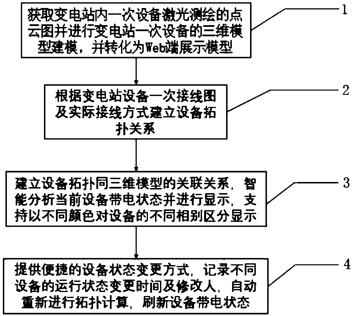
[0031] A live state monitoring method for substation primary equipment based on 3D modeling on the WEB side, such as figure 1 shown, including the following steps:

[0032] Step 1. Obtain the point cloud image of the laser mapping of the primary equipment in the substation and model the 3D model of the primary equipment in the substation, and convert it into a display model on the Web.

[0033] In this patent, live status monitoring is carried out on the following primary equipment in the substation: switches, switches, busbars and connecting lines. The following methods can be used to model the 3D model: 3DMAX, GIS and BIM development platform modeling.

[0034] Step 2. Establish the topological relationship of the equipment according to the primary wiring diagram of the substation equipment and the actual wiring mode.

[0035] The specific...


PUM


Abstract

The invention relates to a method for monitoring the live state of primary equipment of a transformer substation based on WEB terminal three-dimensional modeling, and the method is technically characterized in that a point cloud picture of the laser mapping of primary equipment in a transformer substation is acquired, the three-dimensional model modeling of the transformer substation primary equipment is carried out, and the three-dimensional model is converted into a Web terminal display model; an equipment topological relation is established according to the primary wiring diagram and the actual wiring mode of the substation equipment; an association relationship is established between the equipment topology and the three-dimensional model, intelligently analyzing and a current equipmentlive-line state is displayed, and different phases of equipment to be displayed are supported in different colors; And state change is carried out, operation state change time and modifiers of different devices are recorded, topological calculation is automatically carried out again, and the live state of the devices is refreshed. The substation equipment live-line state monitoring system is reasonable in design, the substation equipment live-line state monitoring working efficiency can be remarkably improved, the number of workers for refreshing the equipment state is reduced, the equipmentstate change situation is recorded, repeated work of equipment wiring topology is checked, and good economic benefits are brought.

Description

technical field [0001] The invention belongs to the field of substation information technology, in particular to a method for monitoring the live state of primary equipment in a substation based on three-dimensional modeling at a WEB end. Background technique [0002] With the growth of power grid business, all kinds of huge data are formed during the planning, design, construction, handover and operation of power grid projects. These data are scattered and stored in different systems in different forms. The forms are complex, the degree of visualization is low, the access methods are limited, and it is difficult to use them effectively. It cannot meet the current and future pursuit of the company in terms of work efficiency and economic benefits of production and operation. The strategic development needs of lean management, cost reduction and efficiency increase. The charged state of the equipment in the substation is basically still in the stage of tabular and two-dimens...

Claims


Application Information

Patent Timeline
Patent Type & Authority Applications(China)
IPC IPC(8): G06F17/50
CPCG06F30/20
Inventor 金石王超易欢欢陈红振蔡剑青余志国郑凤朝杨世勇
Owner STATE GRID HUBEI ELECTRIC POWER COMPANY
Learn More