
A non-explosive metal pipe annular cutting device

A technology for cutting devices and metal pipes, which is applied in wellbore/well components, earthwork drilling, etc., can solve problems such as high operating cost, cutting operation failure, tool damage, etc., achieve good manufacturing and processing technology, and increase the success rate of cutting , the effect of wide cutting range

Active Publication Date: 2012-02-22
NORTH SCHLUMBERGER OILFIELD TECH XIAN
View PDF5 Cites 3 Cited by
  • Summary
  • Abstract
  • Description
  • Claims
  • Application Information

AI Technical Summary

Problems solved by technology

The device disclosed in this patent has the following problems in the actual operation process: the flow direction of the high-temperature fluid does not adopt a smooth transition method, but is directly carried out through the blocking of the piston and the opening of the nozzle, and the high-temperature fluid is easy to form at the nozzle hole. Cycling scour, it is very easy to cause the nozzle holes to communicate with each other after reaming, the tool is damaged, or the solid particles in the high-temperature fluid accumulate to block the nozzle holes, resulting in the failure of the cutting operation
The nozzle hole of the thermal cutter is immersed in the well fluid before operation, and the impurities in the well fluid are easy to deposit on the inner wall of the nozzle hole, which brings unfavorable factors to the normal cutting operation
In addition, the heat insulation material on the inner surface of the heat cutter must be processed with some small holes corresponding to the spray holes of the shell, which increases the complexity of the processing technology, and the shell of the heat cutter is damaged after use, which cannot Repeated use, higher operating costs

Method used


Image

  • A non-explosive metal pipe annular cutting device
  • A non-explosive metal pipe annular cutting device
  • A non-explosive metal pipe annular cutting device

Examples


Embodiment Construction

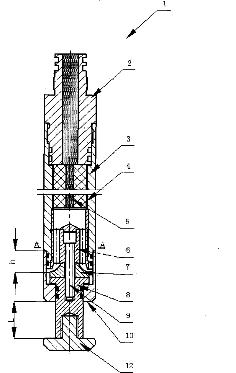
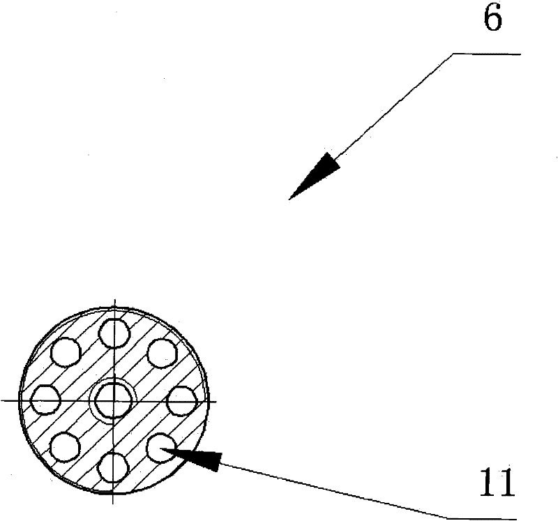
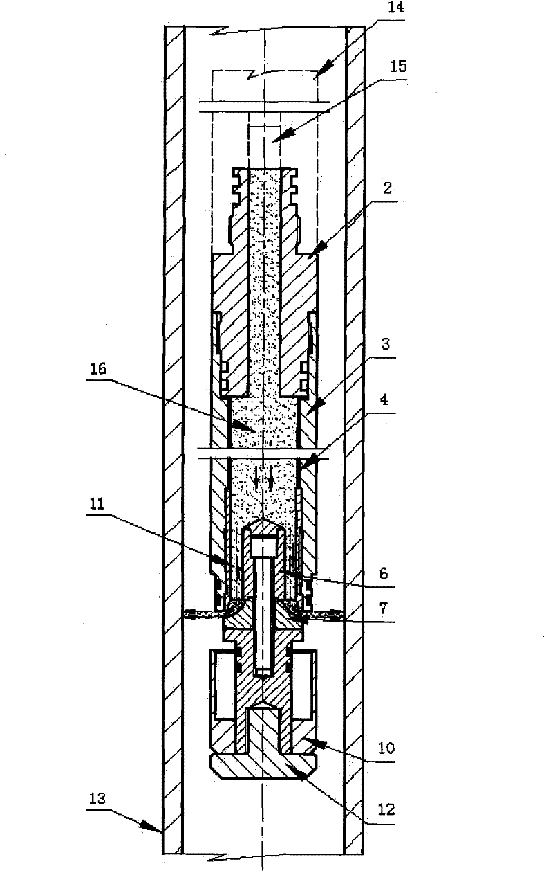
[0020] Such as figure 1 As shown, the non-explosive metal pipe annular cutting device 1 of the present invention mainly includes a cylindrical charge chamber 3, and the upper end of the charge chamber 3 is connected with an upper joint 2 for sealing and installing an ignition device, charge The lower end of the chamber 3 is connected with a sealing sliding sleeve 10; a layer of heat-resistant material 4 is attached to the inner surface of the charge chamber 3, and at least one charge unit 5 is filled in the charge chamber 3, and the other end of the charge chamber 3 is connected with a fluid Distribution deflector 6, deflector 6 is sequentially connected with a conical cone-shaped diverter 7 and tailstock 8 through screw 9, and tailstock 8 is connected with baffle plate 12; on the outside of diverter 7 and tailstock 8 , a sealing sliding sleeve 10 connected with the charge chamber 3 is provided to prevent oil and gas well fluids from entering the interior of the device. Where...


PUM


Abstract

The invention discloses a non-explosive annular cutting device for metal pipes. The device uses the high temperature generated by the burning of scorching agent as the power source, and can cut the metal pipes along the circumferential direction. It is mainly composed of upper joint, charging chamber, fluid distribution deflector, steering gear, sealing sliding sleeve and tailstock and other structures. After the burning agent in the charging chamber is ignited, the generated high-temperature fluid flows along the axial direction of the device to the direction of the fluid distribution deflector. After the high-temperature fluid passes through the fluid distribution deflector, it is turned by the diverter, and its moving direction smoothly changes to vertical In the radial direction of the axial direction of the device, and under the action of pressure, the sealing sliding sleeve slides to the rear of the device to open the cutting channel. The high-temperature fluid directly acts on the inner surface of the metal pipe to be cut, thereby realizing the cutting operation. It can be applied to downhole accident handling when the construction pipe string of oil and gas wells is stuck.

Description

technical field [0001] The invention belongs to the application field of combustion technology, and relates to a cutter, in particular to a non-explosive annular cutting device for metal pipes, which is used for cutting stuck metal pipe strings during oil and gas well construction. Background technique [0002] Glow agent combustion technology is used in a variety of applications such as the destruction of obsolete military equipment, rapid welding repairs of railroad tracks, and various cutting applications. The scorching agent burns at a temperature exceeding 2200°C, which is hot enough to melt most metals. By injecting oxygen to increase the reaction speed of the burning agent, the combustion temperature can reach 5500°C to 8800°C. Such a substantial temperature increase greatly reduces the action time of the cutting target. The slag and gases produced by the combustion are directed in one direction through the orifice, resulting in a high-speed moving, pressurized jet ...

Claims


Application Information

Patent Timeline
Patent Type & Authority Patents(China)
IPC IPC(8): E21B29/02
Inventor 李森元高强郑超民闫峰袁铁刚王宝兴钮元元张俊峰姚元文郭红军
Owner NORTH SCHLUMBERGER OILFIELD TECH XIAN
Learn More