
Method, device and equipment of compression coding and compression coding method

A technology of compression coding and coding method, which is applied in the field of signal compression and compression coding, which can solve the problems of low compression efficiency, high complexity, inability to perform compression coding, etc., and achieve the effect of improving efficiency

Active Publication Date: 2009-12-30
HUAWEI TECH CO LTD
View PDF0 Cites 3 Cited by
  • Summary
  • Abstract
  • Description
  • Claims
  • Application Information

AI Technical Summary

Problems solved by technology

However, due to the inherent information entropy between signals, the vastly different compression efficiencies of different compression schemes for different signals, and the high requirements for complexity in real-time transmission, it is often difficult to maximize the compromise between coding efficiency and complexity signal adaptability
[0003] The lossless compression coding technology in the prior art is mainly applied to audio storage to obtain a higher compression ratio, but this application brings higher complexity
In another technique, each sample point of the signal is compressed and encoded to obtain a larger compression ratio. However, using a single compression mode to compress each sample point of different input signals ignores the consideration of the signal characteristics, and it is very difficult to It is possible to use a compression mode that is not suitable for the input signal to compress and encode the input signal, so that the compression efficiency is greatly reduced, and in severe cases, it is even impossible to perform compression encoding

Method used


Image

  • Method, device and equipment of compression coding and compression coding method
  • Method, device and equipment of compression coding and compression coding method
  • Method, device and equipment of compression coding and compression coding method

Examples


Embodiment 2

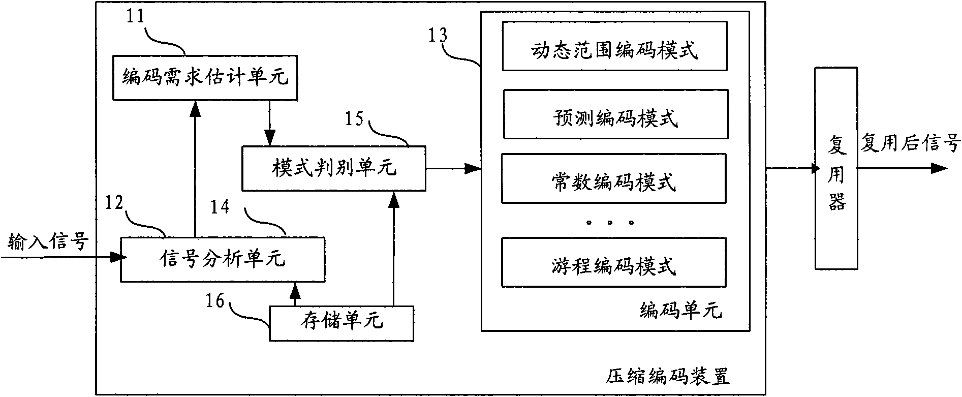
[0023] figure 2 It is a schematic structural diagram of an embodiment of the compression encoding device of the present invention, such as figure 2 As shown, the compression coding device includes a coding requirement estimating unit 11 , a mode judging unit 12 , and a coding unit 13 . The coding requirement estimating unit 11 is used to respectively estimate and obtain the coding requirement value for compressing and coding the input signal frame using the first coding mode and at least one other type of coding mode according to the input signal frame, and the mode decision unit 12 is used to obtain the coding requirement value according to the coding requirement The encoding requirement value obtained by the estimation unit 11 determines the encoding mode adopted by the input signal frame from the above encoding modes according to the mode strategy, and the encoding unit 13 is used to use the encoding mode determined by the mode decision unit 12 to process the input signal...

Embodiment 3

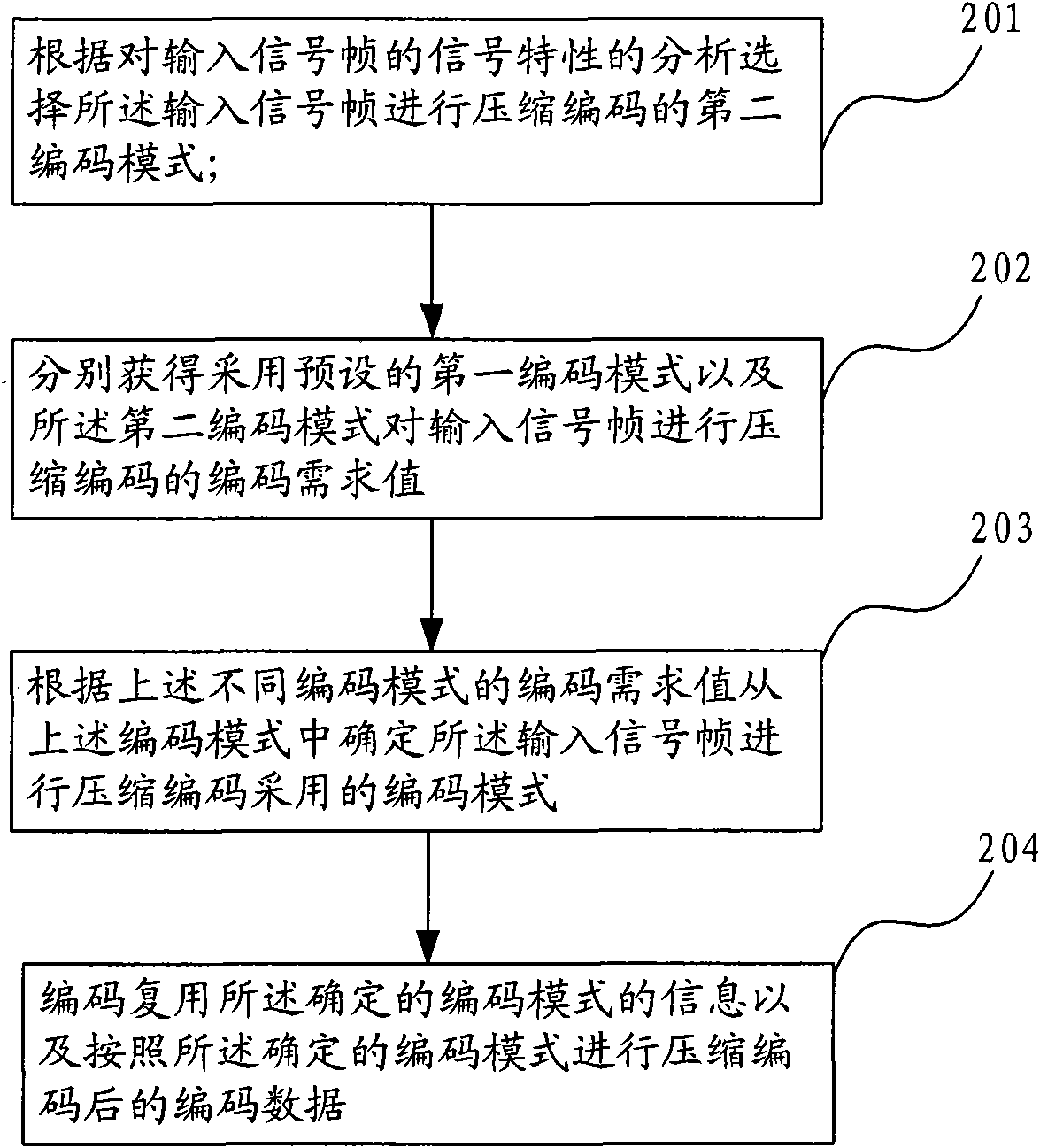
[0070] Image 6 It is a flowchart of an embodiment of the present invention, including:

[0071] Step 601: Obtain encoding requirement values ​​for compressing and encoding input signal frames using the first encoding mode and at least one other type of encoding mode;

[0072] The first encoding mode may be a dynamic encoding mode, and the at least one other type of encoding mode is another encoding mode different from the dynamic encoding mode. When the at least one other type of encoding mode is only one, it may be The predictive mode, of course, does not exclude other encoding modes.

[0073] Step 602: Determine the coding mode adopted by the input signal frame from the above-mentioned coding modes according to the coding requirement value according to the mode policy;

[0074] Step 603: Multiplexing the information of the determined coding mode and the coded data compressed and coded according to the determined coding mode.

[0075] In this embodiment, the coding requir...

Embodiment 4

[0078] Figure 7 It is a flowchart of an embodiment of the present invention, including:

[0079] Step 801: Obtain an encoding requirement value for compressing and encoding an input signal frame using a first encoding mode.

[0080] The step 801 can be realized through at least two implementation methods, one is to compress and encode the input signal frame by frame by using the first encoding mode, and calculate the encoding requirement value required for compression encoding, and the other is to encode the input signal according to the first In the encoding mode, the encoding requirement value required for frame-by-frame compression encoding is estimated to obtain an estimated value of the encoding requirement value.

[0081] The first encoding mode may be a dynamic encoding mode, and the encoding requirement value required by the dynamic range encoding mode may include characteristic information such as the number of bits or bytes required for encoding, which is used to c...


PUM


Abstract

The embodiment of the invention relates to the compression coding technique, which is as follows: a second coding mode selecting an input signal frame according to the analysis of signal characteristics of the input signal frame to carry out the compression coding, respectively obtaining a coding required value carrying out compression coding on the input signal frame by obtaining a presupposed coding mode and the second coding mode, a coding mode adopted for determining the input signal frame from the coding modules and carrying out compression coding according to the coding required value, information of the coding mode determined by coding multiplexing, and coding data which is processed by the compression coding according to the determined coding mode, thus realizing the popularity and preferential selection of the coding mode.

Description

technical field [0001] The embodiments of the present invention relate to the field of signal coding and decoding, and in particular, to a signal compression technology, specifically a compression coding method, device and equipment, and a compression decoding method. Background technique [0002] Lossless compression techniques should save bandwidth and generate distortion-free reconstruction signals, which can effectively improve coding efficiency. However, due to the inherent information entropy between signals, the vastly different compression efficiencies of different compression schemes for different signals, and the high requirements for complexity in real-time transmission, it is often difficult to maximize the compromise between coding efficiency and complexity Adaptiveness of the signal. [0003] The lossless compression coding technology in the prior art is mainly applied to audio storage to obtain a higher compression ratio, but this application brings higher co...

Claims


Application Information

Patent Timeline
Patent Type & Authority Applications(China)
IPC IPC(8): H03M7/30G10L19/00G10L19/22
CPCG10L19/22G10L19/0017
Inventor 苗磊齐峰岩张清
Owner HUAWEI TECH CO LTD
Learn More