Commercial air conditioner

A technology for air conditioners and commercial use, applied in the field of commercial air conditioners, can solve the problems of rising production costs, difficulty in inspection, and compressor burnout, and achieve the effect of improving quality and reducing production costs.

Inactive Publication Date: 2009-12-30
LG ELECTRONICS (TIANJIN) APPLIANCES CO LTD
View PDF0 Cites 1 Cited by
  • Summary
  • Abstract
  • Description
  • Claims
  • Application Information

AI Technical Summary

Problems solved by technology

However, there is the following problem in this prior art one-to-many air conditioner: because the pipe wall of the clamped part B on the branch pipe 80 will be thinned during the above-mentioned clamped process, the compressive capacity of this position is relatively insufficient , the strength test can only withstand the pressure of 55kgf / cm*G, and the high-pressure refrigerant flows inside it, so that it is only suitable for low-pressure systems, and if it is used in high-pressure systems, the wall thickness must be increased. As a result, the production cost increases, and in the long-term operation process, this part often bursts, which seriously affects the quality of the product
In addition, when the port of the branch pipe 83 is welded to the branch pipe connected to the indoor unit, since the distance between the welding part and the clamped part B is very close, it is easy to cause missing welding and desoldering.
In addition, due to the small size of the welding joint, it is difficult to find it during inspection, so there may be refrigerant leakage after a period of operation, resulting in insufficient pressure in the system, and in serious cases, it may cause the compressor to burn out due to overheating

Method used


Image

  • Commercial air conditioner
  • Commercial air conditioner
  • Commercial air conditioner

Examples


Embodiment Construction

[0012] The commercial air conditioner provided by the present invention will be described in detail below in conjunction with the accompanying drawings and specific embodiments. Components that are the same as those in the prior art are assigned the same reference numerals, and detailed description thereof will be omitted.

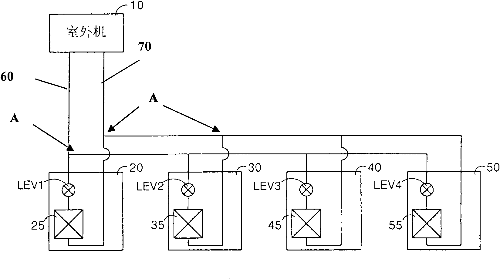
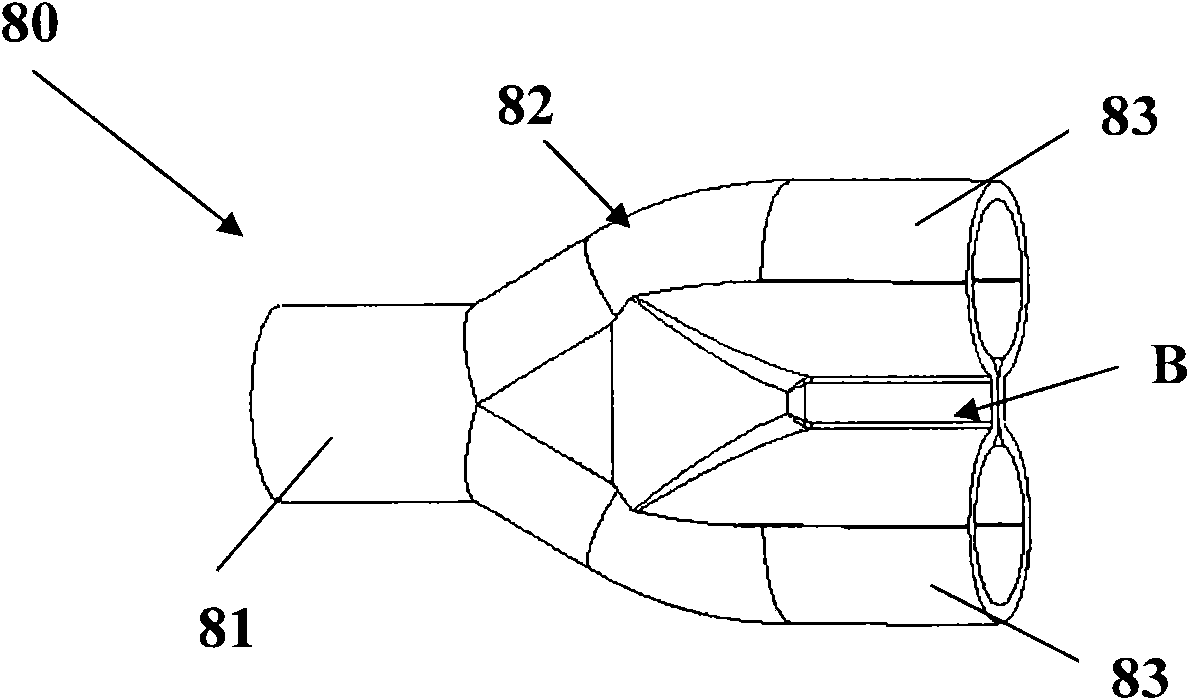
[0013] Such as Figure 3 ~ Figure 4 and figure 1 As shown, the commercial air conditioner provided by the present invention is composed of one or more outdoor units 10 and multiple indoor units 20, 30, 40, 50 connected to each other through refrigerant pipes 60, 70; A compressor that can compress the refrigerant into a high-temperature and high-pressure state not shown in ; an outdoor heat exchanger that can make the refrigerant flowing inside exchange heat with the surrounding outdoor air; it is composed of an outdoor fan and an outdoor fan motor. After the power is turned on, the outside air can be sucked into the inside of the outdoor unit 10, and at ...


PUM


Abstract

The invention relates to a commercial air conditioner. The air conditioner consists of one or more outdoor units and indoor units connected with each other through refrigerant pipes, wherein a joint of a header pipe and each branch pipe on each refrigerant pipe is provided with a bifurcated pipe; the bifurcated pipe is integrally formed by a straight pipe and an inclined pipe, and one end of the inclined pipe is connected with the outer circumferential surface of the straight pipe; and one outer port of the straight pipe is connected with the header pipe, while the other outer port of the straight pipe and the outer port of the inclined pipe are connected with one branch pipe respectively. The commercial air conditioner has the advantages that the bifurcated pipe is integrally formed by the straight pipe and the inclined pipe, and the inclined pipe is made through extrusion forming on the outer circumferential surface of the straight pipe by means of a precise instrument; the machining mode ensures that the pipe wall thickness at the joint of the straight pipe and the inclined pipe is identical to those of other parts; the part does not blow out due to different pipe wall thicknesses during longtime operation, thereby improving product quality; in addition, because no lack of weld and unsoldering is caused during welding, no refrigerant leakage occurs.

Description

technical field [0001] The invention relates to an air conditioner, in particular to a commercial air conditioner. Background technique [0002] An air conditioner is a device that makes its internal refrigerant undergo a refrigeration or heating cycle consisting of a compression process, condensation process, expansion process, and evaporation process, and is usually divided into two types: split type and integrated type. Wherein the split type air conditioner is usually composed of an outdoor unit and an indoor unit which are connected to each other through refrigerant pipes and are arranged outdoors and indoors respectively. When the split type air conditioner is in the refrigeration cycle, the refrigerant compressed by the compressor and turned into a high-temperature and high-pressure state first flows into the outdoor heat exchanger, where the refrigerant will dissipate heat to the outside, then flow to the expansion valve, and flow through The expansion valve signifi...

Claims


Application Information

Patent Timeline
Patent Type & Authority Applications(China)
IPC IPC(8): F24F1/00F25B5/02F25B6/02F25B41/00
Inventor 贾林靖
Owner LG ELECTRONICS (TIANJIN) APPLIANCES CO LTD
Why Eureka
Try Eureka