
Planar motor adopting three-dimensional permanent magnet array

A permanent magnet array, plane motor technology, applied in the direction of holding devices, magnetic circuits, electrical components, etc. using magnetic attraction or thrust, can solve the performance indicators such as affecting the movement stroke, response speed and movement accuracy, and the movement inertia of the plane positioning device is inconsistent. Balance and other issues to achieve the effect of improving acceleration and load capacity, and improving thrust and suspension capacity

Active Publication Date: 2009-12-23
TSINGHUA UNIV +1
View PDF3 Cites 26 Cited by
  • Summary
  • Abstract
  • Description
  • Claims
  • Application Information

AI Technical Summary

Problems solved by technology

The linear drive unit located on the bottom not only bears the drive of the end bearing table, but also bears the mass of the top linear drive unit, thus causing the plane positioning device to move in multiple directions (such as the X direction and Y direction of the traditional XY table) The serious imbalance of motion inertia affects the improvement of performance indicators such as motion stroke, response speed, and motion accuracy.

Method used


Image

  • Planar motor adopting three-dimensional permanent magnet array
  • Planar motor adopting three-dimensional permanent magnet array
  • Planar motor adopting three-dimensional permanent magnet array

Examples


Embodiment Construction

[0019] The specific structure, mechanism and working process of the present invention will be further described below in conjunction with the accompanying drawings.

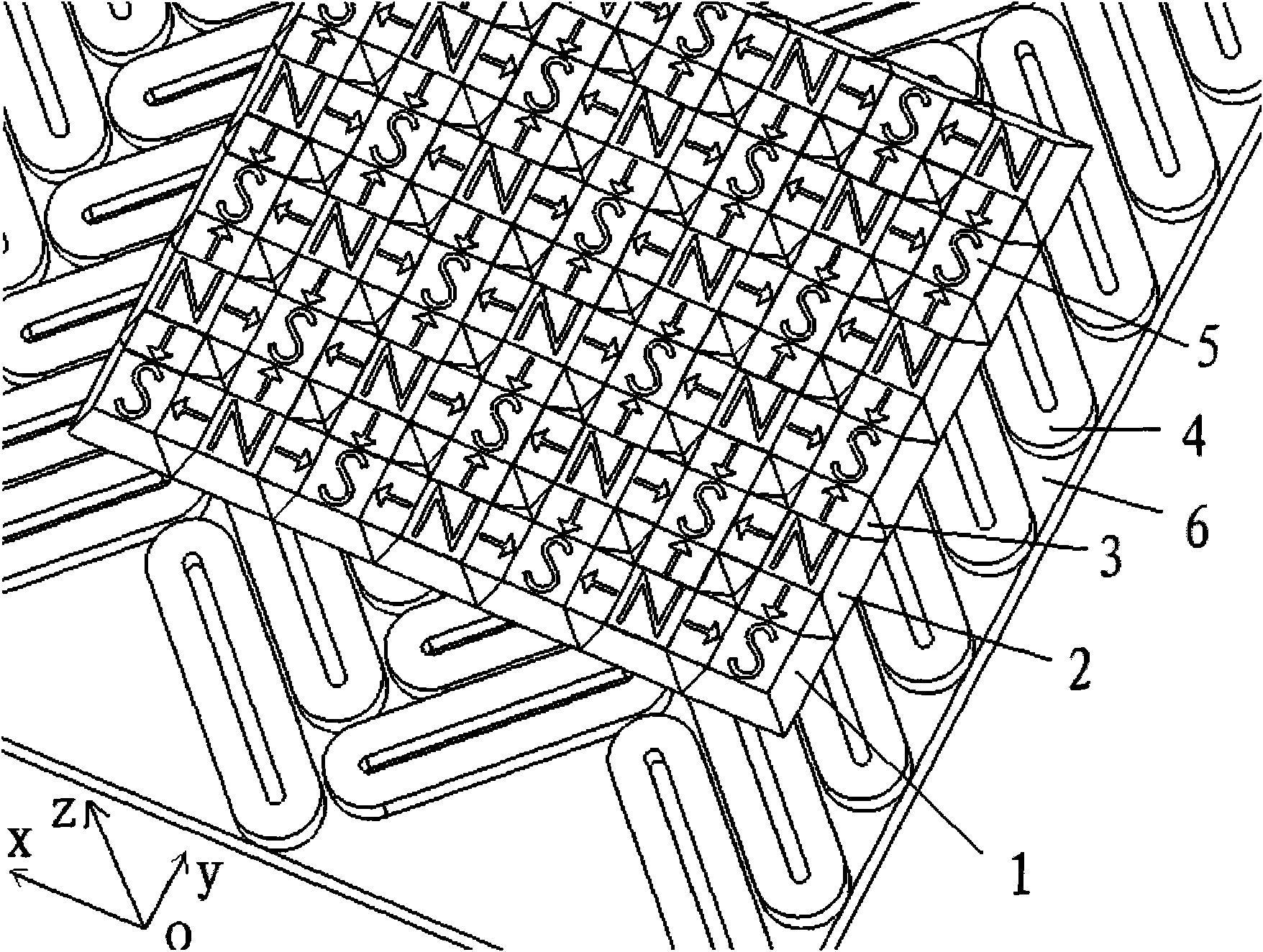
[0020] figure 2 It is a three-dimensional view of the planar motor using a three-dimensional permanent magnet array in the present invention. It can be seen from the figure that the planar motor using a three-dimensional permanent magnet array in the present invention includes a mover 5 and a stator 4, and the mover adopts a three-dimensional permanent magnet array. The permanent magnet array adopts a three-dimensional permanent magnet array. The three-dimensional permanent magnet array consists of an S-shaped regular square prism large permanent magnet 1 with an S pole on the upper bottom, an N-type regular square prism large permanent magnet 2 and a small permanent magnet 3 with an N pole on the upper bottom. The large permanent magnets of the S-type and N-type regular quadrangular prisms are magnetized along ...


PUM


Abstract

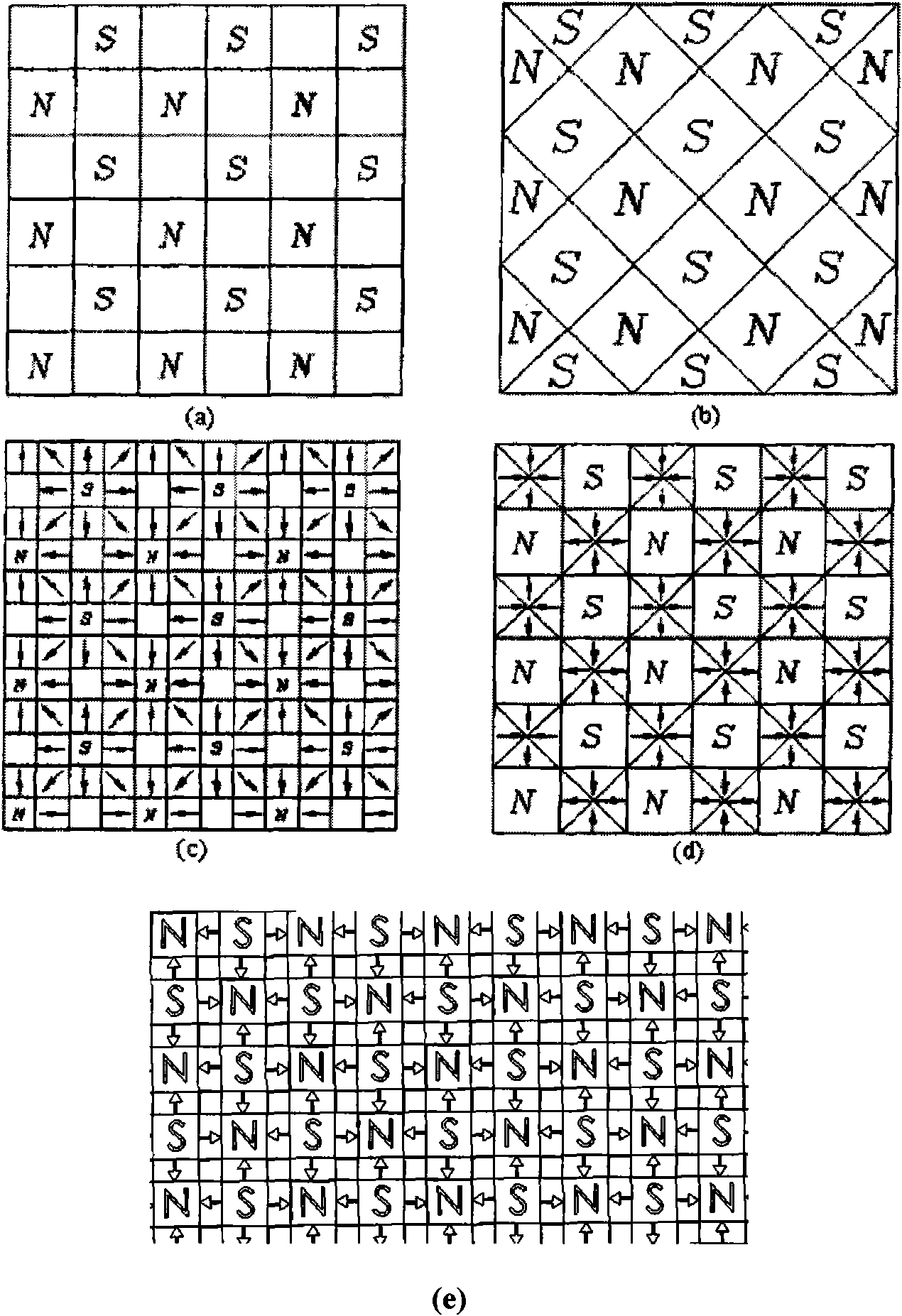
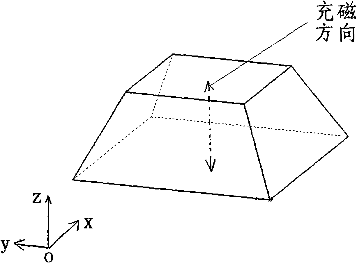
The invention relations to a planar motor adopting a three-dimensional permanent magnet array, and the planar motor comprises a rotor and a stator. The rotor adopts a three-dimensional permanent magnet array, the three-dimensional permanent magnet array consists of S-type and N-type big permanent magnets which are respectively provided with an S-pole upper bottom surface and an N-pole upper bottom surface and both shaped like frustums of square pyramids and a small permanent magnet, the S-type and the N-type big permanent magnets both carry out the magnetizing along the direction of connecting lines of centers of the respective upper and lower bottom surfaces, the small permanent magnet is obtained by symmetrically cutting a quadrangular pyramid from the upper bottom surface and the lower bottom surface of a straight triangular prism with the bottom surface which is shaped like an isosceles triangle, the magnetizing direction is parallel to the direction of the bottom side of the isosceles triangle of the bottom surface, the lower bottom surfaces of the S-type and the N-type big permanent magnets are downward, the S-type and the N-type big permanent magnets are arranged in a staggered manner along the X direction and the Y direction for forming a planar array, the small permanent magnet is arranged between the adjacent two big permanent magnets, and the magnetizing direction of the small permanent magnet is pointed to an S pole of the adjacent S-type big permanent magnet from an N pole of the N-type big permanent magnet. The rotor can generate higher field strength mass ratio in air gap and further improve the thrust and the acceleration of the planar motor.

Description

technical field [0001] The invention relates to a planar motor, in particular to a planar motor using a three-dimensional permanent magnet array, which is mainly used in the fields of manufacturing equipment and robots. Background technique [0002] In many industrial equipment, we need to drive the workpiece or the worktable to move in the plane and position it precisely on the plane, such as the stage of the microscope, the silicon wafer stage in the lithography machine and other equipment. The traditional plane positioning device is composed of two or more sets of linear drive units stacked vertically. Each set of linear drive units consists of a rotary motor, a set of linear motion conversion mechanism and a set of linear guide rails, or a linear motor and a set of linear guides. A set of linear guide rails. The linear drive unit located on the bottom not only bears the drive of the end bearing table, but also bears the mass of the top linear drive unit, thus causing th...

Claims


Application Information

Patent Timeline
IPC IPC(8): H02N15/00
CPCH02K2201/18H02K41/03
Inventor 朱煜张鸣汪劲松闵伟胡金春尹文生杨开明徐登峰段广洪蔡田
Owner TSINGHUA UNIV
Learn More