
Multiple-row linked solar uniform condensing tracking device

A tracking device and solar energy technology, which is applied in the field of solar energy utilization, can solve problems such as increased thermal stress of batteries, uneven strength, battery breakage, etc., and achieve the effect of improving uniformity and reducing output power

Inactive Publication Date: 2011-09-14
王瑞峰
View PDF4 Cites 1 Cited by
  • Summary
  • Abstract
  • Description
  • Claims
  • Application Information

AI Technical Summary

Problems solved by technology

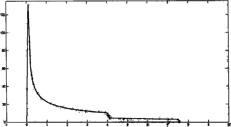
Approximate the sunlight as parallel light. Through calculation, it can be found that the intensity of the light here is very uneven. In some places, the light intensity can reach more than 120 times the intensity of the unfocused sunlight, while in some places it is only a few times. , or even zero, which will not only reduce the output power of the solar cell (at this time the output power of the cell is only 80% to 90% under uniform illumination conditions, see Franklin E.T, Coventry J.S., Effects of highly non-uniform illumination distribution on electrical performance of solar cells. Proceedings of Solar 2002-Australian and New Zealand Solar Energy Society), and more seriously, places with high light intensity have high temperature, which will not only cause damage to the battery, but may also cause large temperature changes A sharp increase in the thermal stress of the local battery, causing the battery to break and cannot continue to be used
Therefore, this continuous reflective condenser is not suitable for systems in which the reflective condenser is fixed

Method used


Image

  • Multiple-row linked solar uniform condensing tracking device
  • Multiple-row linked solar uniform condensing tracking device
  • Multiple-row linked solar uniform condensing tracking device

Examples


Embodiment Construction

[0021] Further description will be made below in conjunction with the accompanying drawings.

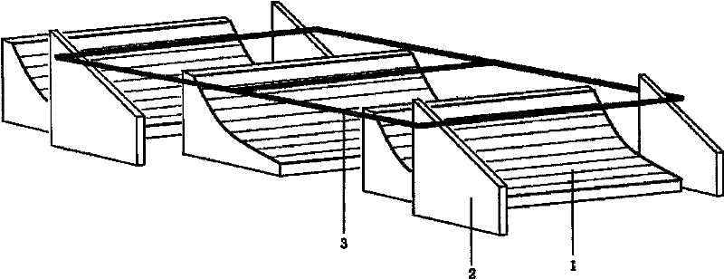
[0022] See figure 1 . The present invention is a multi-row linkage type solar energy uniform concentration tracking device, which includes several linear Fresnel reflective concentrators 1, two sets of inclined guide rails 2 at the front and rear, a horizontal frame 3 installed with light energy conversion components and a transmission device (not shown). Show). The left and right guide rails of each group of inclined guide rails 2 are arranged on the left and right sides of the linear Fresnel reflective condenser 1 , and the transmission device drives the horizontal frame 3 to move back and forth along the inclined guide rails 2 . The inclined guide rail 2 adopts a frame structure, which can minimize the shading of sunlight. Since the transmission device belongs to the known technology, it will not be described in detail here.

[0023] Each Fresnel reflective condenser is compo...


PUM


Abstract

The invention relates to a multiple-row linked solar uniform condensing tracking device, comprising a plurality of reflecting condensing mirrors, a front inclined guide rail group, a rear inclined guide rail group, a horizontal frame provided with a light energy conversion part and a transmission device; the left guide rail and the right guide rail of each group of inclined guide rails are respectively arranged at the left side and the right side of the reflecting condensing mirror; and the transmission device drives the horizontal frame to move back and forth along the inclined guide rails. The reflecting condensing mirror is a linear Fresnel reflecting condensing mirror consisting of multifaced and slender plane reflecting mirrors, wherein, each plane reflecting mirror corresponds to different tangent planes of same reflecting condensing curve surface, and coincides with or is parallel to the tangent planes; and under the premise that the included angle of any two plane mirrors is constant, the up-and-down position of each plane reflecting mirror along the optical axis is not limited. The multiple-row linked solar uniform condensing tracking device can obtain light spots with uniform condensation, improve uniformity of light intensity distribution on the light energy conversion part, therefore, the battery is not damaged and the output power of a photovoltaic cell is not reduced.

Description

technical field [0001] The invention relates to a solar energy uniform concentration tracking device, in particular to a multi-row linkage type solar uniform concentration tracking device, which belongs to the field of solar energy utilization. Background technique [0002] In the field of solar energy utilization, reflective condensers are usually used to reflect and concentrate sunlight to light energy conversion components. For example, in Chinese patents CN201110661Y and CN1361397A, an axisymmetric parabolic concentrator is used, and another example is the parabolic mirror in Chinese patent CN2090950U. [0003] If the reflector is a continuous parabolic cylindrical mirror, when the sunlight irradiates obliquely, the light intensity distribution of the focused spot of the reflector is very uneven. Such as figure 2 As shown, the unit of the x-axis in the figure is centimeters. If the focal length of the parabolic cylindrical mirror is 1 meter, and the mirror width is al...

Claims


Application Information

Patent Timeline
Patent Type & Authority Patents(China)
IPC IPC(8): H01L31/052H01L31/0232H01L31/02G05D3/00H02S20/32H02S40/22
CPCY02E10/52Y02E10/50
Inventor 王瑞峰
Owner 王瑞峰
Learn More