Filament drawing device

A spinning device, monofilament technology, applied in filament/thread forming, complete equipment for producing artificial threads, non-woven fabrics, etc., to achieve uniform ventilation and sensitive adjustment

Inactive Publication Date: 2009-12-23
OERLIKON TEXTILE GMBH & CO KG
View PDF1 Cites 2 Cited by
  • Summary
  • Abstract
  • Description
  • Claims
  • Application Information

AI Technical Summary

Problems solved by technology

[0004] Despite this measure, there is always the risk of formation of thin sections (defects) in the nonwoven due to uneven laying of the filaments and formation of strands of filaments in the nonwoven

Method used


Image

  • Filament drawing device
  • Filament drawing device
  • Filament drawing device

Examples


Embodiment Construction

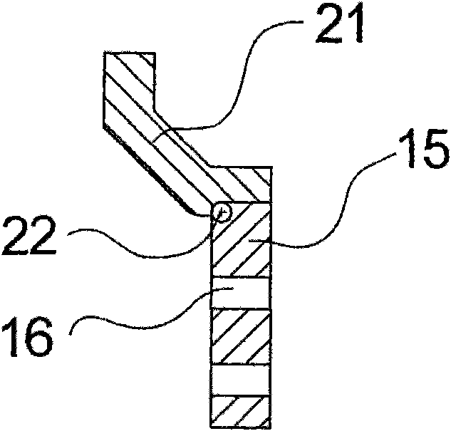
[0058] figure 1 An apparatus for melt spinning monofilaments and drawing the monofilaments into a nonwoven fabric according to the present invention is shown in . The molten polymer is fed from a melt source 1 , such as an extruder, via a melt conduit 2 to a spinning device 3 . The spinning unit 3 here contains a pump, not shown, for increasing the pressure and for metering the melt. Arranged on the underside of the spinning device 3 is a spinning nozzle 4 through which the melt is extruded into thin filaments which leave the spinning device 3 in the form of filament tufts 5 . The spinning nozzles 4 can be formed, for example, in a plurality of spinning nozzle plates arranged one after the other perpendicular to the plane of the drawing. Here perpendicular to the plane of the figure is set to have ratios in the plane of the figure and at figure 1 Several orders of magnitude more spinning nozzles 4 than those shown in . The monofilament cluster 5 thus has the shape of a cur...


PUM


Abstract

The present invention relates to a device for drawing melten spinning filaments to form spinning-cement type nonwoven fabric. Filaments are guided by a slit-shaped nozzle, and the nozzle guides compressed air and filaments are transferred by drawing the nozzle. Two sides of a slit locating on the downstream of a slit-shaped opening are provided with guide elements which are designed to form a nonwoven uniform structure, namely one guide element is provided with a plurality of grooves parallel to the transfer direction, and the guide element facing said guide element is provided with a plurality of holes for making the space between guide elements to be connected with environment in a passive manner.

Description

technical field [0001] The invention relates to a device for drawing a plurality of monofilaments according to the preamble of claim 1 . Background technique [0002] Such a device for producing spunbond nonwovens is known from US 2006 / 0172024. In order to manufacture spunbonded non-woven fabrics, the molten polymer input from the extruder is spun into a plurality of monofilaments through one or more rows of linearly arranged spinneret holes in a spinning box, and then with the aid of a cooling device cool down. A traction force is exerted on the monofilament for drawing by means arranged at a distance below the monofilament, ie a drawing nozzle in the form of a slit, which traction force causes the monofilament to be stretched and conveyed. For this purpose, compressed air flows out from the inner wall of the drawing nozzle in the direction of feed of the filaments, thereby exerting the desired pulling force on the filaments. The monofilaments are laid in a random manner...

Claims


Application Information

Patent Timeline
IPC IPC(8): D04H3/02D01D13/02B29C48/345
CPCD04H3/005D01D5/0985D04H3/16
Inventor H·舍特勒D·萨波里迪斯
Owner OERLIKON TEXTILE GMBH & CO KG
Why Eureka
Try Eureka