
Line connector for media lines

A catheter connector and catheter technology, applied in the direction of pipes/pipe joints/fittings, machines/engines, pipeline heating/cooling, etc., can solve problems such as functional impact

Active Publication Date: 2009-12-16
VOSS AUTOMOTIVE
View PDF0 Cites 25 Cited by
  • Summary
  • Abstract
  • Description
  • Claims
  • Application Information

AI Technical Summary

Problems solved by technology

This will affect some functionality

Method used


Image

  • Line connector for media lines
  • Line connector for media lines
  • Line connector for media lines

Examples


Embodiment Construction

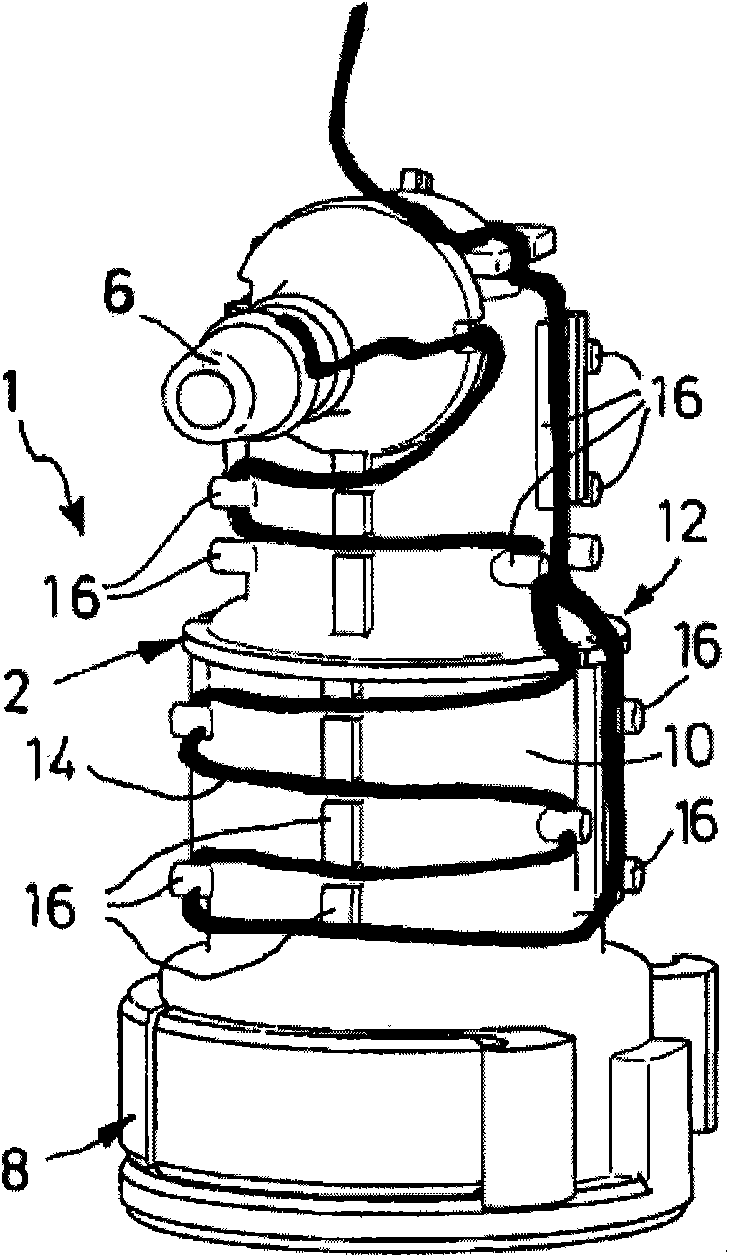
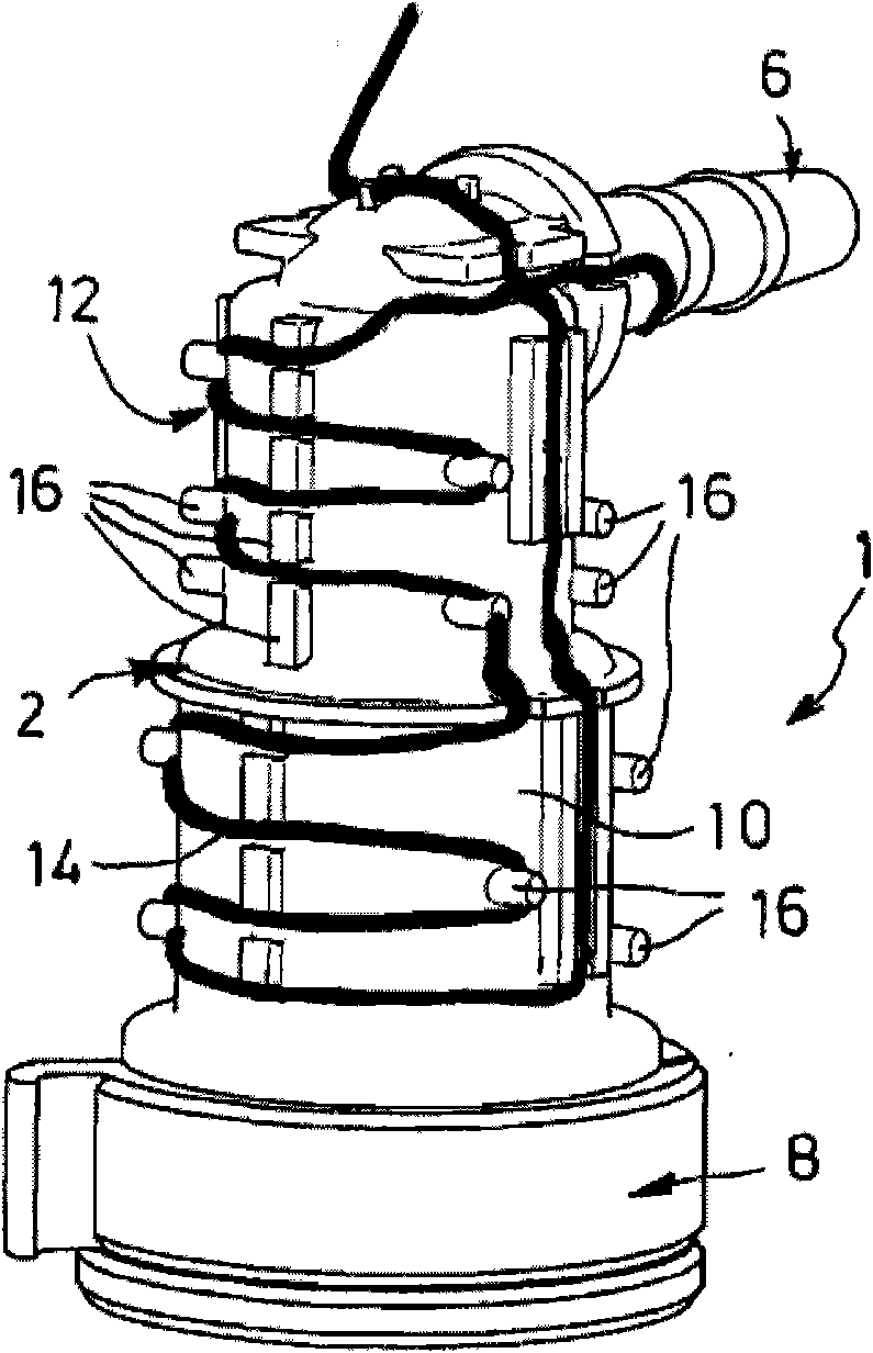
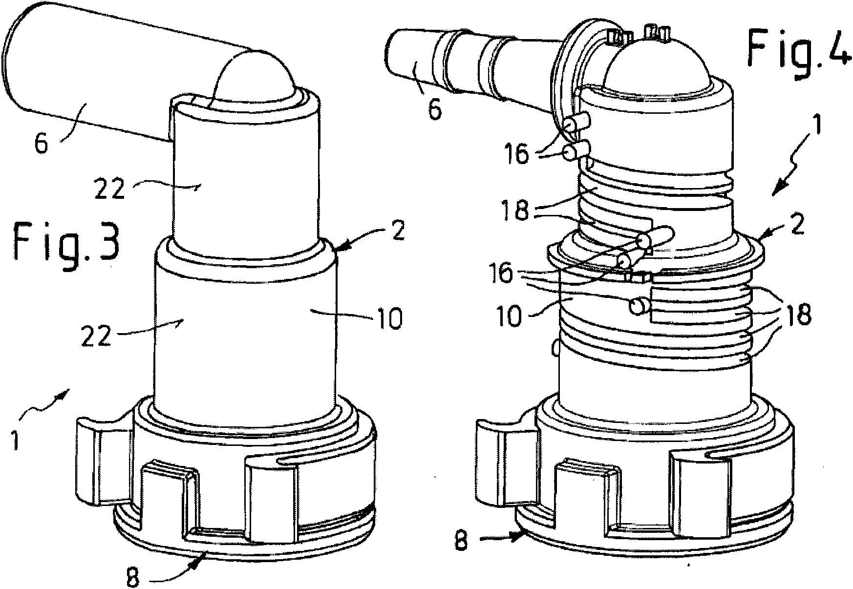
[0028] The catheter connector 1 according to the invention comprises a connection head 2, preferably in the form of a plastic, in particular a fibre-reinforced polyamide such as PA6.6 GF30 or PA12 GF30 One-piece molded parts. The connection head 2 has at least one connection section 6 for connection to a medium line 4 (shown only in FIGS. 7 and 11 ) or to any other assembly not shown in the figures. Furthermore, the connection head has a further connection section 8 opposite the connection section 6 , which is designed in a known manner, for example in the form of a sleeve for a detachable plug connection. The connecting section 8 can of course also be designed as a plug-in section.

[0029] In the described preferred embodiment, the connection head 2 is configured as an angle connector, wherein the connection sections 6 and 8 comprise a corner at an angle, for example a right angle (90°), to their connection axis. The connecting sections 6 , 8 are here connected via a tran...


PUM


Abstract

The present invention relates to a line connector (1) for media lines, comprising a connecting piece (2) having at least one connection section (6, 8) for the connection to a media line (4) or to an assembly, and having a transitional section (10) comprising a flow channel (11), the section adjoining the connection section (6, 8). To this end, electrical heating means (12) are provided at least in the region of the transitional section (10) in an arrangement that at least partially surrounds the flow channel (11). The invention further relates to an assembled media line comprising a pipe line having a heating conductor (29) arranged on the circumference thereof, and a heatable line connector attached to at least one pipe line end of the media line.

Description

technical field [0001] The invention relates to a conduit connector for a medium conduit, in particular a line or hose for a hydraulic fluid medium, comprising a connection head having at least one connection for connection to a medium conduit or a complete plant segment and a transition segment adjacent to the connecting segment, the transition segment having an internally disposed fluid channel. [0002] Furthermore, the invention also relates to an assembled media conduit using such a conduit connector. Background technique [0003] Such a line connector is used for joining at least two medium lines or for connecting at least one line to any desired system, in particular to a motor vehicle. In motor vehicles, media are often conveyed through conduits which, due to their high freezing point, tend to freeze at higher ambient temperatures, which are quite possible depending on climatic changes. This will affect some functions. E.g. water pipes for window washer systems an...

Claims


Application Information

Patent Timeline
Patent Type & Authority Applications(China)
IPC IPC(8): F16L53/00F16L53/38
CPCF16L25/01F01N2610/10F16L53/008H05B3/42F01N2610/14F01N2610/02F16L53/38
Inventor 奥拉夫·博格迈尔爱德华·布吕克乌尔里希·埃尔布赖纳·格林德尔马丁·莱希纳弗兰克·彼得斯萨沙·罗森费尔特奥特弗里德·施瓦茨科普夫艾哈迈德·居恩迪茨马尔科·伊森堡
Owner VOSS AUTOMOTIVE
Learn More