Impeller of rotor for shaftless transmission pump

A technology of rotor impeller and shaftless transmission, which is applied in the direction of pumps, pump components, non-variable pumps, etc., which can solve problems such as difficult management, leakage, and high cost, and achieve the effect of less contact friction

Inactive Publication Date: 2009-12-16
广州水泵厂有限公司
View PDF0 Cites 1 Cited by
  • Summary
  • Abstract
  • Description
  • Claims
  • Application Information

AI Technical Summary

Problems solved by technology

[0002] The impeller of the existing pump has a central hole connected to the rotating main shaft. The power of the impeller is transmitted from the prime mover through the main shaft. The rotating shaft of the pump needs to extend out of the pump body to connect with the prime mover. If the pressure is different, the liquid will leak out along the rotating shaft of the pump. For this reason, a sealing device for the pump shaft needs to be installed. The sealing device for the rotating shaft of the existing pump generally includes two types: packing seal and mechanical seal. It can also be mainly divided into single-end mechanical seal and double-end mechanical seal. Among them, although the packing seal has the advantages of simple maintenance and low price, it cannot solve the leakage problem in the process of conveying liquid media, so it must not be used for conveying toxic and harmful. Inflammable, explosive and expensive liquids; the single-end mechanical seal can achieve basically no leakage when it is first used, but once the mechanical seal is damaged, the leakage will not be controlled immediately, so it is generally not used to transport toxic, harmful, flammable and explosive liquids; Since the double-end mechanical seal structure can be equipped with an independent spacer fluid lubrication and operation system, it can theoretically achieve no leakage of the delivery fluid medium, but it still cannot solve the pollution of the spacer fluid medium from the delivery fluid medium. To achieve no leakage at all, it must Closed management and post-process treatment of the spacer fluid medium are expensive and difficult to manage, and it is impossible to solve the pollution of the spacer fluid medium to the conveying fluid medium, which is unacceptable under many working conditions

Method used


Image

  • Impeller of rotor for shaftless transmission pump

Examples


Embodiment Construction

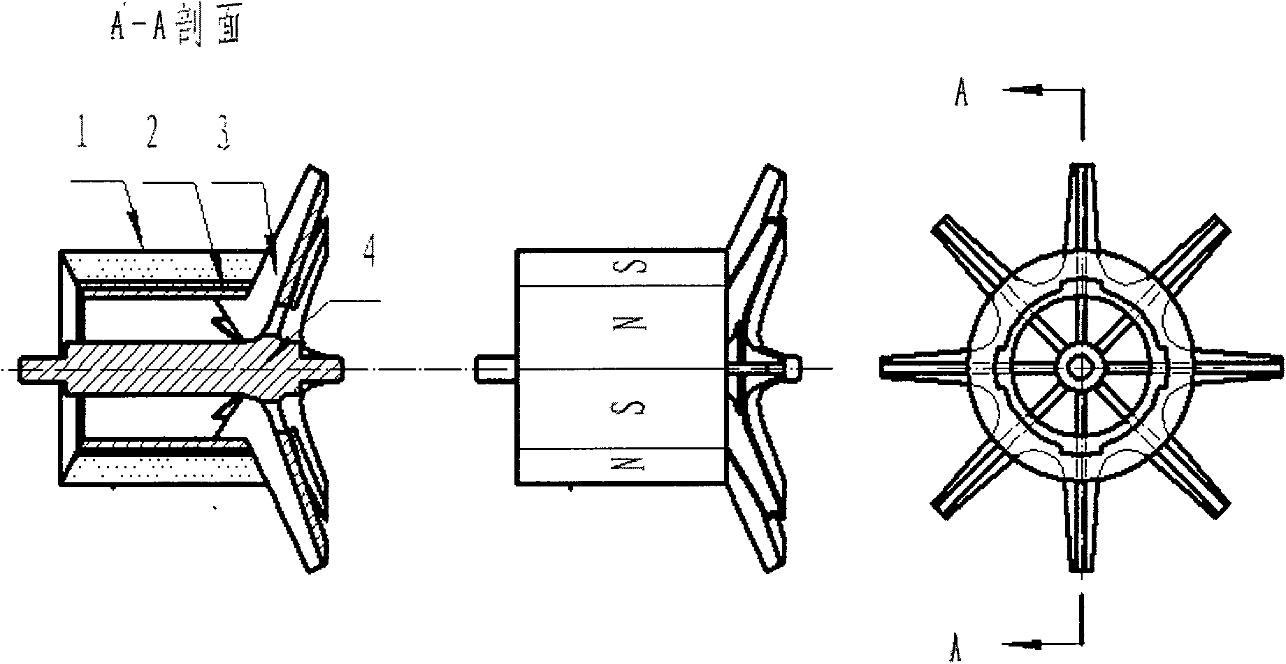
[0009] A shaftless drive pump rotor impeller according to the present invention is composed of a permanent magnet ring (1), a mouth ring (2), a blade (3), and a hub (4), and the mouth ring (2), blade ( 3), the hub (4) is molded integrally with a non-magnetic material, and the permanent magnet ring (1) is molded with ferrite and radially magnetized, and several pairs of N-S are formed on the outer cylindrical surface of the permanent magnet ring. The magnetic pole and the inner circle of the permanent magnet ring have grooves closely matched with the convex grooves on the outer circle of the mouth ring to form a rotor impeller for a shaftless transmission pump.


PUM


Abstract

The invention relates an impeller of a rotor for a shaftless transmission pump aiming to provide an impeller of a rotor for a pump without a transmission shaft and other related elements. The impeller of the rotor for the shaftless transmission pump comprises a permanent-magnet ring, a mouth ring, blades and a hub; wherein, a small section of protruding thin shaft formed at the two ends of the hub is fixed and hung on the related sliding bearings, a plurality of pairs of N-S magnetic poles are arranged on the external circular cylindrical surface of the permanent-magnet ring on the impeller of the rotor; when a stator of the shaftless transmission pump matching the N-S magnetic poles generates alternating magnetic field, the impeller of the rotor rotates to work; the power which drives the impeller of the rotor to do work comes from the torque power of the permanent-magnet ring thereof so that the impeller of the rotor is not needed to be driven by the pump shaft and has no sealing problem of a rotating shaft, thus optimizing the structure and property of the pump and being particularly applicable to the high-efficiency low-energy consumption zero leakage shaftless transmission pump.

Description

technical field [0001] The invention relates to a rotor impeller, in particular to a rotor impeller for a shaftless transmission pump. Background technique [0002] The impeller of the existing pump has a central hole connected to the rotating main shaft. The power of the impeller is transmitted from the prime mover through the main shaft. The rotating shaft of the pump needs to extend out of the pump body to connect with the prime mover. If the pressure is different, the liquid will leak out along the rotating shaft of the pump. For this reason, a sealing device for the pump shaft needs to be installed. The sealing device for the rotating shaft of the existing pump generally includes two types: packing seal and mechanical seal. It can also be mainly divided into single-end mechanical seal and double-end mechanical seal. Among them, although the packing seal has the advantages of simple maintenance and low price, it cannot solve the leakage problem in the process of conveyin...

Claims


Application Information

Patent Timeline
IPC IPC(8): F04D29/18
Inventor 陈自强
Owner 广州水泵厂有限公司
Why Eureka
Try Eureka