
Steam cleaner

A technology for cleaners and steam generators, applied in the field of steam cleaners, can solve problems such as the difficulty of assembling the casing, and achieve the effects of improving heat insulation, simplifying assembly, and being easy to operate.

Inactive Publication Date: 2009-11-18
ALFRED KARCHER GMBH & CO KG
View PDF4 Cites 0 Cited by
  • Summary
  • Abstract
  • Description
  • Claims
  • Application Information

AI Technical Summary

Problems solved by technology

However, special care must be taken when assembling the housing
It can also be provided that the two housing halves are sealed in the region of their joining by a seal, but this makes the housing difficult to assemble

Method used


Image

  • Steam cleaner
  • Steam cleaner

Examples


Embodiment Construction

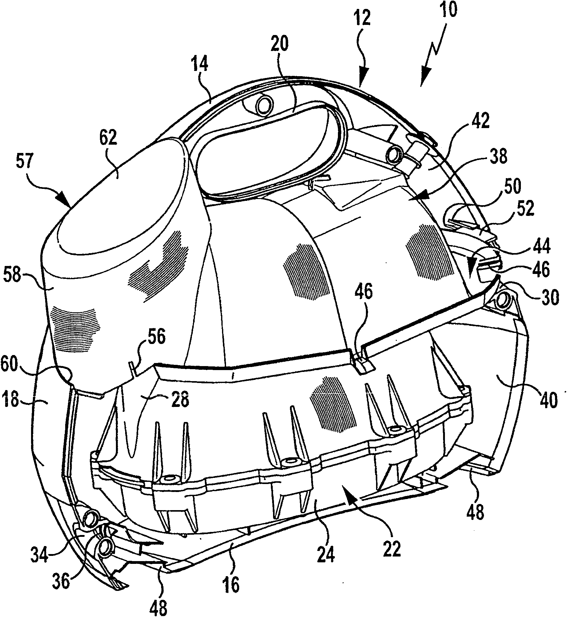
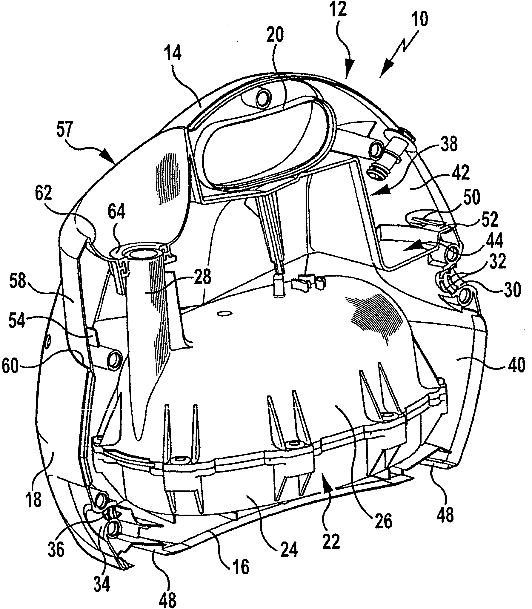
[0022] In the drawing there is shown a steam cleaner generally designated by the reference numeral 10, which has a housing 12 which consists of two housing halves which can be assembled together, only one housing being shown in the drawing Half-shell 14, on which a correspondingly designed housing half-shell can be placed. The two housing half-shells respectively form half of a bottom wall 16, on which a convexly curved side wall 18 is integrally connected, and a handle 20 is formed in its upper area facing away from the bottom wall 16, so that the user can follow the The steam cleaner 10 is shipped in a canister.

[0023] The housing 12 accommodates a steam generator with an electrically heatable steam boiler 22 . The steam boiler is designed in two parts and comprises a lower part 24 and an upper part 26 which are screwed together in a liquid-tight manner. Molded onto the upper part 26 is a filling socket 28 , the free end of which can be closed by a known and therefore no...


PUM


Abstract

The invention relates to a steam cleaner having a housing which encloses a steam generator with an electrically heated steam boiler for generating steam which can be applied to an object to be cleaned On the surface, wherein the housing has two housing halves that can be assembled together. In order to improve the steam cleaner so that it can meet the requirements of a reliable splash protection in an economical manner, it is proposed according to the invention that the housing accommodates a protective cover extending between the two housing halves, the protection The hood covers the steam boiler.

Description

technical field [0001] The invention relates to a steam cleaner having a housing which encloses a steam generator with an electrically heated steam boiler for generating steam which can be applied to an object to be cleaned On the surface, wherein the housing has two housing halves that can be assembled together. Background technique [0002] This steam cleaner is used to clean different surfaces, especially hard surfaces such as floors. It includes a steam generator with an electrically heatable steam boiler for evaporating a liquid cleaning agent, for example for evaporating water. The steam generated can then be applied to the surface to be cleaned. [0003] A steam cleaner is known from utility model DE 201 11 327 U1, in which the housing is formed from two housing half-shells. The half-shell shape of the housing enables economical machining. In order to avoid possible penetration of spray water into the housing interior, it can be provided that the matching edge reg...

Claims


Application Information

Patent Timeline
Patent Type & Authority Patents(China)
IPC IPC(8): B08B3/02A47L11/34
CPCB08B3/026B08B2230/01
Inventor B·贝克K·科普卡
Owner ALFRED KARCHER GMBH & CO KG
Learn More